It is customary to consider the output resistance of the non-inverting amplifier as being zero, but why is that? An Op Amp’s own output resistance is in the range of tens of ohms. Still, when we connect the Op Amp in a feedback configuration, the output resistance decreases dramatically. Why?
To answer these questions, let’s calculate the output resistance of the non-inverting amplifier.
It is widely accepted that the output resistance of a device can be calculated using a theoretical test voltage source connected at the device output. The input, or inputs, are connected to ground. Nevertheless, instead of using this method, let’s try a different one: The small signal variation method.
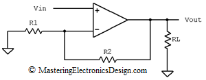
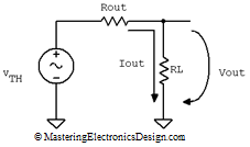
Figure 1 shows the non-inverting amplifier, which drives a load, RL. This circuit has an equivalent Thevenin source as in Figure 2.
Figure 1
Figure 2
From Figure 2, one can see that the output voltage, Vout, can be written as
| (1) |
If we keep VTH constant and apply small variations to Vout, by varying RL for example, the Vout variation, noted ΔVout can be written as follows:
| (2) |
Equation (2) shows that, when the load current increases, the load voltage decreases due to the output resistance. They vary in opposite direction and that is why the negative sign that appears in the Rout calculations is canceled out.
Equation (2) also tells us that we can use a small signal variation method to determine Rout. If, instead of ΔVout and ΔIout we write the small signal notation vout and iout, the output resistance becomes
| (3) |
Let’s apply this method to the non-inverting amplifier.
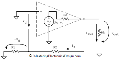
Figure 3
An ideal Op Amp can be represented as a dependent source as in Figure 3. The output of the source has a resistor in series, Ro, which is the Op Amp’s own output resistance. The dependent source is Ao vd, where Ao is the Op Amp open-loop gain and vd is the differential input voltage. The input differential resistance, between the Op Amp inputs, is considered high, so I removed it for simplicity. The same with the common mode input resistances, between the non-inverting input and ground and the inverting input and ground. The non-inverting input is connected to ground, because a fixed value voltage source does not bring any change from a small-signal variation point of view. Thus, we are in line with the general rule that the output resistance of a circuit is calculated with the circuit inputs connected to ground.
Inspecting the loop made by Ao vd, Ro, and RL, vout can be expressed as in the following equation.
| (4) |
where iout is the small variation load current and if is the small variation feedback current.
The differential voltage vd appears across R1, but with negative sign, so if is
| (5) |
And vout becomes
| (6) |
At the same time vd depends on vout.
| (7) |
After replacing vd in equation (6), the resulting mathematical expression depends on vout and iout as in equation (8).
| (8) |
Based on (3) and (8) Rout is
 |
(9) |
Ao is large, about 100000 or 100 dB. Therefore, the second term of the denominator is predominant.
 |
(10) |
This proves that the output resistance of the non-inverting amplifier is
| (11) |
where ACL=1+R2/R1 and it is the closed-loop gain of the non-inverting amplifier. For a proof of the closed loop gain read this article, MasteringElectronicsDesign.com:How to Derive the Non-Inverting Amplifier Transfer Function.
As equation (11) shows, the output resistance of the non-inverting amplifier is several orders of magnitude smaller than that of the Op Amp, because Ro is divided by the operational amplifier open loop gain. Therefore, the non-inverting amplifier output resistance can be considered zero.


What will be the output resistance of this circuit if we suppouse that in this circuit(figure 1) RL doesn’t exist, and the resistor R2 will be our load resistance?
If R2 is your load resistance, one lead is connected to the op amp output and the other lead is connected to ground. In this case, the noninverting input of the op amp is connected to ground, so the op amp is in open loop. As such, the output resistance is Ro.
Correct. No feedback path exists.
What is the dependence of load resistance on opamp gain?
The load and gain do not depend on each other. However, if the load is too small, beyond the op amp output current capability, the output current limit may be triggered. As a consequence, the op amp output signal swing will be reduced.
If I have to drive a tone control circuit that needs a source impedance of 38k ohms how to determine the output impedance of the non-inverting amplifier to match this requeriment?
If you calculate the output resistance with equation (10) you will find out that it is less than one ohm. So, all you have to do is to add a 38k resistor in series with the non-inverting amplifier output. 38k sounds very high for a source resistor. Are you sure about that value? Your tone control circuit should have high input impedance. Otherwise the 38k resistor will make a voltage divider with the tone control input impedance and the signal will be attenuated accordingly.
The value of 38k is suggested in the tone stack calculator program from http://www.duncanamps.com in the tab fender.
Excuse me, but I don’t speak your language very well, I speak brazilian portuguese.
Your English is fine, don’t worry about it. As for the 38k value, if this is what’s recommended, then use my advise in my previous post.
I have a non-inverting op amp with a 50k ohm feedback resistor and R1 of 1k ohm to ground. The 50kohn resistor is connected to three individual resistors (1k, 25k, 100k) to ground via a SPST. I need to know at each resistor position, is the gain the same? if not, how do I calculate the Gain at each resistor position?
You say that the 3 resistors are connected to the 50k. So they can be connected either at the op amp output or the op amp inverting input. If they are connected at the op amp output, the gain is the same no matter which resistor is switched in. They are simply the load of the non-inverting amplifier. If they are connected at the op amp inverting input, the gain is (1 + 50k/(R1||R)) where with R1||R I noted the R1 resistor in parallel with one of the switched in resistors 1k, 25k, 100k.
I like your link and its very useful.
If i were to add a Resistor to the positive terminal, which then goes to ground, how would that affect the system?
It will not affect the Rout calculation because, in figure 3, you can see that there will be no current going through this resistor.
What the resistor will do, in the circuit in figure 1, it will simply lower the input impedance of the amplifier. The new input impedance will be the added resistor value.
How did you get equation 7? Is it from Vd/Vout = (R1+R2)/R1 ? Why is it negative?
Look at Figure 3. The feedback current if flows through R2 and R1. The voltage drop on R1 is equal with vd, but negative, due to the Kirchhoff law on the loop made by the non-inverting input, the inverting input, R1 and ground. So we can write the feedback current as being
if = -vd / R1.
Also, on the loop made by vout, R2 and R1 we can write the equation
vout = if * (R1 + R2).
And since if = -vd / R1, the equation can be written as
vout = -vd/R1 * (R1 + R2).
Uhmmm…No.
if=Vd/R1 (Passive sign convention, IMHO, that’s an error in the calculation…)
Vout = -if (R1+R2) , again, passive sign convention.
Then, Vout = -(Vd/R1) * (R1+R2), that’s anyway correct.
The fact that if = Vd/R1, without the minus sign, lead to an error in the final Rout formula where the part (R0/R1+R2) has to have a minus sign.
Actually, the equations are correct. Figure 3 shows that if * R1 + vd = 0 (with the current sense I chose for if)
Therefore if = -vd / R1.
The same Figure 3 shows that Vout = if (R1 +R2).
Equation (11) shows Rout which is correct. Ro/(R1 + R2) cannot be negative, as you say, because that would make Rout negative. A negative resistor means that it has energy (has a power source) which would not make sense in this case.
I can’t understand why the positive input of the op can be seen as connect to ground?
For fixed value voltage source?If I use a sinusoidal source , equation(10) cannot be used anymore?
The output resistance does not depend on the input source, being it DC or sinusoidal. It is a fixed value. This article shows a method to calculate the output resistance, when feedback is present. Because Rout does not depend on the input source, the input is connected to ground for this calculation.
Hello all. while the Ro of the non-inverting or inverting amplifier is very low for small signal that is not the case at all for large signals (MPP close to 2Vcc). Does anyone have the derivation for this scenario. Ro large signal is in the 300-400 ohm range
Do both the inverting and non-inverting topologies have the same output impedance? I am noticing that they will be the same circuit when calculating output impedance?
Hello,
please note, that Ao has a complete frequency dependent form that is usually estimated as a 2 or 3 pole System (the opamp itself is a 2 or 3 pole System). This means, Ao(w)=(Ao*w1*w2*w3)/(s+w1)(s+w2)(s+w3). All this stuff means that as frequency increases, Ao greatly decreases and eventually the output impedance of the opamp becomes very high. All the calculations in the above post only applies to DC voltages. If you build a regulator circuit with an opamp for example to work on 50kHz, you might want to have a look at the output impedance at 50kHz and check what the voltage drop is inside the opamp that causes an error on the input of the next stage.
That is correct. The article talks about the output impedance in band.