This calculator determines the RMS value of a trapezoidal waveform. Figure 1 shows the waveform and its parameters. All you need to do is to input the time values t1, t2, t3, the signal period T and the signal amplitude Vp. Each time has to have the same units. If you set t1 in microseconds, as an example, all the other time values, t2, t3 and T have to have the same units, microseconds. Vp is a voltage level, in Volts, but the calculator can also be used for currents.
Waveforms
How to Calculate the RMS Value of an Arbitrary Waveform
Previous articles on MasteringElectronicsDesign.com talked about how to calculate the RMS of simple signals like a sine wave, trapezoidal and triangle signals, pulse and square signals. But, what about an arbitrary waveform? How do we calculate its RMS? Starting with the definition, as shown in previous articles, applying the integral, might not be an easy task. We need a different method. Enters the square root of the sum of squares.
The RMS value based on the square root of the sum of squares
If we have a few signals going through the same heating element, each signal heats the element independently of the other signals. This is valid, as long as the signals can be considered uncorrelated, that is, independent one of each other. The formula can be written as follows:
How to Derive the RMS Value of a Sine Wave with a DC Offset
I noticed a question posted on one of Yahoo’s Q&A sites, asking what is the RMS value of a sine wave with a DC offset. The chosen answer as being “the best” was actually wrong. The next comment, which was trying to correct “the best” answer, was wrong too. I am not going to post the Yahoo link here. What I can do, is to show how to derive the RMS value of such waveform.
Let’s derive first the RMS value of a sine wave with no DC offset
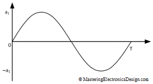
Let’s start with the RMS value of a sine wave, with no DC offset, which is shown in Figure 1. It is well known that the RMS value of a sine wave is 0.707 times the signal peak level, but how can you prove this?
As shown in this article, MasteringElectronicsDesign.com: How to Derive the RMS Value of a Trapezoidal Waveform, or other RMS articles in this website , let’s start with the RMS definition.
The RMS Value of a Trapezoidal Waveform – Part 2
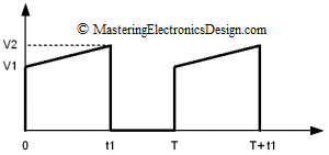
In a previous article, MasteringElectronicsDesign.com:How to Derive the RMS Value of A Trapezoidal Waveform – Part 1, I showed how to derive the RMS value of a trapezoidal signal with a flat plateau and different rise/fall time values. In some applications, the trapezoidal signal plateau is not flat, but rather a ramp, as shown in Figure 1. A typical example is a DC-DC converter, where the transformer winding current might look like the signal in Figure 1. Of course, in the DC-DC converter example, the amplitude is current and not voltage. No matter, the calculations are the same.
This waveform is still considered a trapezoidal waveform. Let’s calculate its RMS value.
Using the Summing Amplifier as an Average Amplifier
Sometimes people ask how can one use a summing amplifier as an average amplifier. The answer is simple, provided that one knows what kind of average one needs.
The summing amplifier can output the average of two, three or more signals. This is different than a signal average. The summing amplifier cannot, for example, output the average of a triangle signal. For that, you need an integrator to perform the average in the analog realm, or you need to sample the signal and calculate the average with a microcontroller. This type of average is the signal average in the time domain. I will write an article about the average of a signal in a near future.
In this post I will show you how to average two or more signals with a summing amplifier. In How to Derive the Summing Amplifier Transfer Function I wrote that the summing amplifier shown in Figure 1
How to Derive the RMS Value of Pulse and Square Waveforms
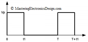
The RMS value of a pulse waveform can be easily calculated starting with the RMS definition. The pulse waveform is shown in Figure 1. The ratio t1/T is the pulse signal duty-cycle. As shown in other articles in this website (MasteringElectronicsDesign.com:How to Derive the RMS Value of a Trapezoidal Waveform and MasteringElectronicsDesign.com:How to Derive the RMS Value of a Triangle Waveform), the RMS definition is an integral over the signal period as in equation (1).
How to Derive the RMS Value of a Triangle Waveform
What is the RMS value of a periodic signal? When a periodic signal is generated by a source connected to a load, a resistor for example, the RMS value is the continuous signal, the DC value which would deliver the same power to the load as the periodic signal.
This article shows how to derive the RMS value of triangle waveforms with different shapes and duty cycles.
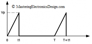
The triangle waveform in Figure 1 has a slower rise time than the fall time. In this case, the fall time is small so that it can be considered zero. If it is not zero, read further on deriving the RMS value of a triangle with comparable rise and fall times.


