I noticed a question posted on one of Yahoo’s Q&A sites, asking what is the RMS value of a sine wave with a DC offset. The chosen answer as being “the best” was actually wrong. The next comment, which was trying to correct “the best” answer, was wrong too. I am not going to post the Yahoo link here. What I can do, is to show how to derive the RMS value of such waveform.
Let’s derive first the RMS value of a sine wave with no DC offset
Let’s start with the RMS value of a sine wave, with no DC offset, which is shown in Figure 1. It is well known that the RMS value of a sine wave is 0.707 times the signal peak level, but how can you prove this?
 Figure 1
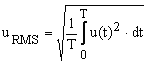
As shown in this article, MasteringElectronicsDesign.com: How to Derive the RMS Value of a Trapezoidal Waveform, or other RMS articles in this website , let’s start with the RMS definition.
 |
(1) |
The sine wave time dependency can be described by the following function:
| (2) |
T is the function period, or T = 1/f where f is the waveform frequency. Also, a1 is the amplitude.
Replacing (2) in (1), and calculating the integral over a full period T, we find the RMS value squared as in the following equation:
 |
(3) |
The standard method to calculate a squared sine integral is to transform it into its double angle equivalent, using a trigonometric identity usually called the power-reduction formula.
 |
(4) |
So the RMS squared becomes
 |
(5) |
If you’re wandering why the sine term is zero in the previous equation, that’s because
 |
(6) |
Therefore, the RMS value of a sine wave with offset zero is the following well known formula,
| (7) |
The RMS Value of a Sine Wave with a DC Offset
 Figure 2
Now, let’s look at a sine wave with a DC offset. This waveform is shown in Figure 2 and is described by the following function.
| (8) |
where with a0 I noted the DC offset. Applying the RMS definition, the RMS squared can be written as:
 |
(9) |
Let’s calculate the integral.
 |
(10) |
 |
(11) |
 |
(12) |
 |
(13) |
 |
(14) |
Therefore, the RMS value of a sine wave with a DC offset is given by the following expression.
 |
(15) |
The immediate verification of the validity of this expression is the RMS value of a sine wave with zero DC offset. Indeed, when a0 = 0 V, the RMS level reverts back to equation (7), which is 0.707 of the sine amplitude.
Expression (15) can also be verified by comparing it with Parseval’s Theorem. This theorem says that the integral of the square of a function is equal with the integral of the squared components of its spectrum. In effect, the theorem states that the total energy of a waveform can be found in the total energy of the waveform’s Fourier components. In our case, a0 is the DC level, or the frequency zero component, and a1 is the fundamental frequency. There are no other Fourier components. As such, the RMS value of a sine wave with a DC offset as given by expression (15) is correct.


Helped me refresh some theory
Glad to hear that. Come back soon.
Sine wave having rms value =100v is superimposed with 50 v DC supply ?
You need to reformulate your question. I do not understand what is it that you are asking.
So do “True RMS” multimeters read this value correctly if there is a DC offset on a sine wave – or are they really AC coupled and read the RMS value of the AC component only? If I owned a true RMS meter, I would try it myself – but alas, I don’t.
You need to check the datasheet of the multimeter. Not all of them are capable of measuring the RMS value of an AC signal riding on a DC level. I would not take that for granted, even if it says “true RMS measurement”. Most manufacturers will make sure to write this capability in the multimeter feature list.
I was highly skilled in Math in a previous life. Ever since then, I forgot most of my teachings. After reading this article, my memory gradually began to be refreshed. Thank you.
Thanks, correct apart from the last line! Either u-squared OR root the RHS!
Thank you for seeing that typo. I fixed it.
infinite thanks sir,specially why the sine term becomes zero,I searched lot on that your’s explanation is best.
RMS really points to the “heating” enregy present in any waveform. So be it Sine wave or DC voltage riding on it irrespective of the polority of any component the final effect of all the components is governned by superposition theorm, provided the effective bandwidth is infinite or close to it.
Superposition only applies for a linear function.
Since RMS is not linear you can’t use superposition.
Excellent article, sir and thank you for this website.
For the purposes of an actual answer, doesn’t “a1” need to be the peak of the non offset sinusoid, not the peak of the shifted sinusoid(as shown in your figure 2)?
Yes, that is the case, as figure 1 shows. I’ll make sure to make it clearer on figure 2 by adding/subtracting a1 from offset. Thank you for your comment.
I just calculate the RMS value using integration method, by hand, immediately after I saw this title and then scroll to the bottom of your article to check whether I’ve a correct answer. But when “spectrum power” shows, I realize I wasted my time, 🙂
Sure, you do not need to start with the integral, unless you want to verify my calculations. It is, indeed, a waste of time. Just apply the formula and you’re done.
Which is the answer to pure dc of RMS 0 or 1
Are you asking what is the RMS value of a DC signal? That is the DC signal level.
Wouldn’t it be easier to explain the answer as “the square-root of the sum of squares” of the RMS components?
RMS of DC = DC or a0
RMS of AC = ACpk/sqrt(2) or a1/sqrt(2)
RMS of combination = sqrt(a0^2 + a1^2/2)
This approach makes more complex functions easier to address. For example, add a triangular wave with amplitude a2 riding on this offset sine:
RMS of triangle = Peak/sqrt(3)
RMS of combo = sqrt(a0^2 + a1^2/2 + a2^2/3)
Your comment is correct regarding the calculation of RMS values based on the square root of the sum of squares. I am not sure that it is simpler though. In any case, this subject is part of a planned article I am writing in this series about RMS calculation. Not everybody understands the root square of the sum of squares and I plan to explain it in the near future. In this article I showed the derivation of the RMS value starting from the definition.
Thank you for your input.
much simpler. all anybody needs to understand is that when you take say RMS, you are taking the Mean of the Square, so that means the Square is what is important, and you have to work in Squares. the Root is just to convert back to the units you started with after your work in Squares is done. obviously the Squares here are because Watt=VV/Ohm so were by working in Squares were treating power as the most important quantity and doing our voltage calcuations so that they give the right power calculations, power being proportional to the Square of the voltage.
Hey!
I am musician and am interested how a digital DAW would read pure DC offsets RMS and peak dbs. Any ideas on this? I think a sine with DC offset would end up being louder on the meter and with higher peak.
By DAW you mean a Digital Audio Workstation, right? From my time in the professional audio industry I know that offsets are dreaded in this business. So, I am not sure why you would have DC offsets getting into your DAW. But, if this is the case, DAW will digitize whatever it “sees” in the input, like a digital oscilloscope would. Then it will calculate the RMS of the signal with the square root of the sum of squared samples. I did not write an article about this method for calculating the RMS but I will in the near future. Generally, I do not think a signal with DC offset will sound louder. And that’s because a speaker does not generate sound due to DC, just a loud pop when the system is turned on.
why the square in u(t)^2?
The RMS value represents the signal power, so the integral has to be of the u(t)^2. Without that square, you would calculate the average of the signal. In case of a simple sine wave the average is 0. If the sine wave has a DC offset as in this article, the average value is the DC offset.
Thank you.
Thanks very much, but I have one question that keeps bugging me.
Why is the RMS calculated as the sqrt of the avg of the squares as oppose to the avg of the sqrt of the squares.
In other words why use sqrt((1/n)*(x1^2+x2^2…..xn^2))
Why not use (1/n)*(sqrt(x1^2)+sqrt(x2^2)…….sqrt(xn^2))
sqrt(x1^2) = x1, right? So, in effect, you want to use the signal average (1/n)(x1 + x2 +…+ xn) to calculate the RMS, which is not correct. RMS represents power. Therefore, first calculate the sum of each component power. Once the power is calculated perform a square root of this sum to calculate the actual voltage.
Ok, so if x^2 is the power of the signal and you get them mean of x^2 ie the mean of the power than why do we than take the sqrt of the mean.
Thanks
Because the mean of xk^2 results in Volts to the power of two, which is equivalent with Watts, the units of power. So, to bring this back to rms voltage, you need to perform the square root of the result.
Very convincing and clear explanation. Thank you very much!
Extending this idea, the RMS of a waveform made by summing known simple waveforms has an RMS that is the square root of the sum of the squares of the component RMS values if the component waveforms are orthogonal.
Correct. That will be the subject of another article. Thank you for your comment.
This article is very good and another article can generalize the results illustrated by the following example with the necessary proofs.
If two time functions x and y are absolutely uncorrelated (r[xy] = 0) then the rms value of their sum can be found in the way so described above.
If two time functions x and y are absolutely correlated (r[xy] = 1) then the rms value of their sum can be found as the linear sum of the two rms values of x and y.
If two time functions x and y are partially correlated (e.g. r[xy] = .5) then the rms value of their sum can be found as the linear sum of the two rms values calculated in the two cases above divided by two for r[xy] = .5
Should add the qualification: the two time functions x and y are what we call in EE power signals, existing for extended time.
Thank you Thomas. Great input.
helped a lot …
Great contribution, Adrian.
Back to the the top and your clear derivation of the rms of a constant dc+sine wave. Now, can I still use equation 15 when my dc term ao is a decaying exponential ie ao = e^(-t/Tau)? I guess yes giving a rms value that is depends on time instant t. Am I correct?
My second question is: my sine wave is now multiplied by a decaying exponential term like ao above giving u(t) = e^(-t/T) x sin((wt). Again my intuition tells me the rms must also reduce with time ie must be a function of time instant t but what would the rms equation be?
From your description it looks like your signal in both cases is aperiodic. So, equation 15 does not apply. You can still calculate the RMS if you take a window of the signal and apply the Fourier transform. Then calculate the RMS with the square root of the sum of squares of the Fourier components.
Thanks. Admittedly, I am very rusty on these things having graduated in 1983.
However, I think both my signals are indeed periodic with a period equal to 20 ms for a frequency of 50Hz and w = 2xPIx50. My first signal is
u1(t) = e^(-t/Tau) – cos(wt), and Tau is equal to, say, 30ms, so that after about 150 ms, the decaying dc offset vanishes and only the alternating cosine wave remains. So, after 150ms, the rms should be equal to 0.707 but for earlier times, the DC component should have an rms value and hence my thinking that your equation 15 can still be used.
My 2nd function u2(t) = e^(-t/Tau) cos(wt), also appears periodic and eventually decays to zero. Now, since I have only one term, my guess is that the rms is equal to e^(-t/Tau)/sqrt(2) which makes it time -dependent but I cannot prove it.
Since a periodic signal is the signal that repeats itself at regular intervals, both your signals are not periodic in the strict mathematical sense. The peak in the first cycle is not at the same level as the peak in the second cycle. It looks periodic, but it is not. Your first example is the sum between a periodic signal and a decaying signal. The signal becomes periodic after the decaying one disappears. That is why I said that you need to study this signal in intervals.
If you take a scope with RMS measurements capability, you will see that the RMS value varies as the decaying signal reduces to zero. You need to calculate the RMS starting with the definition, in a chosen window, but I agree it is complicated. So, probably it is better to use numerical computation, the same way a digital scope will do. Here are two methods:
1. You sample the signal with a certain sampling frequency over a window of a few cycles. Then apply the FFT on those samples. Then you calculate the RMS for that window with the square root of the sum of squares of the Fourier components.
2. Approximation: Consider the DC signal of your first function fixed over the first cycle. The value is the DC value at the beginning of the cycle. Calculate RMS1 for that cycle with eq. 15. Then consider the DC signal fixed over the second cycle. The value is the DC value at the beginning of the second cycle. Calculate RMS2 for that cycle with eq. 15. And so on, up to say 10 cycles. Then add them with the square root of the sum of square. It is an approximation, but a close one to reality and it will be over a window of 10 cycles.
Same methods apply for your second example.
Your suggested 2nd method gives me exactly what I need; a sufficiently accurate approximation of each rms value for each cycle and the reduction with time of each rms value until the DC disappears.
All is crystal clear now with a bit of rust falling off my brains.
Very many thanks for your time and help.
nice explanation..easily understood
Thank you so much for this explanation Adrian. Your ability to explain these things is exceptional! I am no mathematician, so I can’t follow all your proofs, but I get the drift of the principle involved. Just one small question: does the same principle to an all-positive sinusoidal – eg, one that varies between +5 and +15 volts? By the standard definitions of AC, this would be reckoned a DC current/voltage, and it confuses me whether or not AC Theory can be applied to a DC waveform. Or, perhaps it’s just a question of definitions, and where you place your X-axis. Thanks again for this blog.
Sorry, meant Y-axis (also omitted an “apply” in fourth line!)
Mike, thank you for the review.
Regarding your question, yes, it does apply. Your sine wave has a peak to peak voltage of 15-5 = 10V. So it is a sine wave with an amplitude of 5V and it rides on top of a DC level of 10V. At the peak the value it is 10V DC plus 5V amplitude equals 15V. At the bottom it is 10V DC minus 5V amplitude equals 5V. So, the principle is the same, and you can apply equation 15. The RMS value is
sqrt(10^2 + (1/2) * 5^2) = 10.607V
Hi Adrian,
You wrote:
“”The RMS value is sqrt(10^2 + (1/2) * 5^2)””
Well, that is sqrt(100 + 12.5).
Sqrt of 112.5 is in my humble opion 10.60660 V.
Right??
I can not see how you arrive at 35.35V
Also, a VRMS will never be more that the maximum Voltage value of the signal; that should set off an alarm!
Regards
Jan
Jan, thank you for pointing this typo out. I made the correction.
thank you
If the integration of sine function is corresponding to average value then why do not we use average value instead of RMS value ( I mean the area under the graph of sine finction is the same as the area we can get from straight line of 0.6366 the average value)
That is incorrect. It is not the integration of the sine function. It is the integration of the sine function plus offset squared. And it cannot be 0.6366 because the RMS value depends on both the offset value and the sine wave amplitude.
What happen if AC signal totally shifted to first quarter, i,e if only exist positive alternating current?
Then what will the signal name?? DC signal or AC signal???
It is still an AC signal.
i have a question
if we have a simple circuit
consists of
alternating voltage source ( pure sine wave ) and a pure resistance with frequency 50 hz
my question is
if we raise the frequency of the soure more than 50 hz
the power consumed in the resistor will changed or not )
It will not change. The RMS value of a sine wave is peak_voltage/sqrt(2). As you can see, it does not depend on frequency.
Hi, I’m not as advanced as you guys, so this will probably sound stupid. But I want to plot the RMS value of an AC sine wave (1V peak amplitude) on a graphics calculator. Is the correct function simply:
y=1/?2sin(x) or
y=1/?2sin(x)+1/?2
And with a 3VDC offset, is it:
y=1/?2sin(x)+3 or
y=1/?2sin(x)+3/?2 or
y=1/?2sin(x)+3+1/?2
Thanks in advance.
Sorry, those question marks were supposed to be square root symbols.
The RMS value of a sine wavelength does not depend on your variable x. It is peak_voltage divided by sqrt(2). So the graph will be a straight horizontal line, in your case 1Vpk/sqrt(2) = 0.707V.
Clearly depicted the concept. Thanks a lot.
Thanks for this. I’m curious – how would you calculate the average power of a non-ideal capacitor or inductor that was subjected to a sine wave with a DC offset? In other words how would you calculate the power if the phase angle between the voltage and current in an offset AC waveform is a non-ideal value?
For the capacitor, only the sine wave counts. The RMS value of the AC component is raised to the power of two and multiplied with the capacitor ESR (Equivalent series resistance).
For the inductor, take the RMS value of the signal, as calculated in this article and multiply it with the inductor DCR (DC resistance).
However, at different frequencies, the amplitude of the AC component varies, because both the inductor and capacitor present a reactance that depends of the capacitor/inductor value and signal frequency. So you need to calculate the signal amplitude before calculating the RMS value.
I tried to read through most of the Comments, but hope I didn’t miss this important feature of the (15) equation.
I thought it very interesting that u(rms) = sqrt ((a(0)^2 + a(1)^2)/2) rather than
simply u(rms) = a(o) + a(1)/sqrt 2.
One might intuitively think the a(0) DC offset might add to the AC rms directly rather than increase the u(rms) value as a 90 degree out of phase component.
On a second look, what happened in (13) equation to the term 1/T(2/w)a(0)a(1)(cos 2pi-cos 0)? Doesn’t that become (2/pi)a(0)a(1)?
No, it becomes zero, because cos(2pi) – cos(0) = 0
It is a (rare) pleasure to find an article that answers a question that had come up with an analysis that is clear and correct. Thanks.