Norton’s Theorem is a powerful tool for solving electrical circuits. Like Thevenin’s Theorem, it simplifies the circuit one needs to study and dramatically reduces potential calculation errors.
Norton’s Theorem states that networks with voltage and current sources, as well as resistors are electrically equivalent to one single current source and one single resistor in parallel with the source. The theorem is valid for AC circuits, where instead of resistors there may be reactive components. Since this theorem sounds very much like Thevenin’s Theorem, one can only imagine that Norton’s current source is equivalent with Thevenin’s voltage source. Indeed, they are equivalent as we will see further.
To demonstrate how powerful this theorem is, let’s take the same circuit we studied in How to Apply Thevenin’s Theorem – Part 1. This article describes how to apply Norton’s Theorem for a circuit with independent sources. Circuits with dependent sources have to be treated differently by Norton’s Theorem. We will see that in a future article.
Figure 1
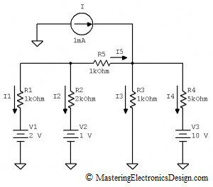
The circuit to be studied is shown in Figure 1. We would like to calculate the current through the R2 resistor and then find out all the other currents.
If we attempt to write the loop and node equations for this circuit we will have to have 5 equations, 3 loop and 2 node equations with 5 unknowns: I1, I2, I3, I4 and I5. Not very difficult to solve, but we can do better.
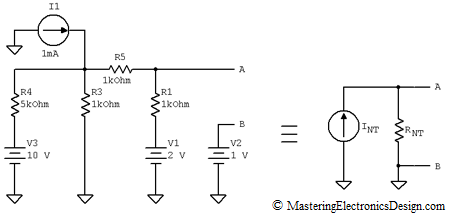
First, let’s redraw the schematic as in Figure 2. We eliminated R2 and will calculate the Norton equivalent current source at A-B, which is shown to the right.
Figure 2
With the elimination of R2 the circuit simplifies. The Norton equivalent source is well defined if we calculate the Norton current, noted here INT, and the Norton resistor, RNT. Once INT and RNT are known, we will reconnect R2 at the source A-B output and determine its current. This calculated current through R2 is equal with the current that flows through R2 in Figure 1, because the given circuit and the Norton source are equivalent.
What is the method to find the Norton equivalent source of this circuit?
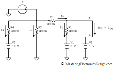
The Norton current can be determined by applying a short circuit at the A-B output. Isc is the short circuit current and it is equal with INT.
Figure 3
Now, this is still a circuit with 3 loop equations and 2 node equations. This system of equations still has 5 unknowns, in which I2 was replaced by Isc. However, this is simpler than the circuit in Figure 1, and here is why: The drop on R2 is gone. Because of that, I1 can be easily calculated from the V1, R1, V2 loop.
Next, if we find I5, then Isc, which is the Norton current INT, can be calculated from the node equation
And here is why the calculations are simpler. We are left with 3 unknowns, I3, I4, I5 which we can find with the following 3 simple equations:
We only need I5 in this system. To solve it, first we eliminate I3 from the first 2 equations and then eliminate I4 from the resulting equation and the last one in the system. The result is I5 = 0.818 mA.
Knowing I5, the Norton current, INT is
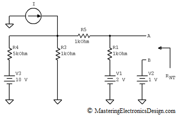
The next step is to determine the Norton resistance, RNT. This is the resistance seen at A-B, as in Figure 4.
Figure 4
Being a circuit with independent sources, the rule is to replace the voltage sources with short circuits and the current sources with open circuits. After doing that, we can see that RNT is R1 in parallel with R5, which is in series with the parallel value of R3 and R4. Therefore, RNT is
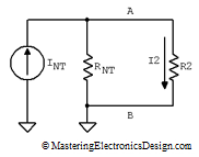
Now that we know INT and RNT we can draw a simple circuit to find the R2 current, by applying Norton’s Theorem. The current through R2 in Figure 1 is equal with the current through R2 in Figure 5.
Figure 5
R2 and RNT form a current divider. Therefore, I2 is
This result shows that the Norton current source is equivalent with the Thevenin’s voltage source. If we compare this result with I2 as calculated in How to Apply Thevenin’s Theorem – Part 1, we can see that the Norton current is
and that the Norton resistance equals the Thevenin resistance.
>>> <<<
If we need to calculate the rest of the currents in Figure 1, we can take advantage of the current we already know, I2.
I1 is easy to be found from the V1, R1, R2, V2 loop.
Then I5 = – (I1 + I2) = – 0.332 mA. From V2, R2, R5 and R3 loop, I3 is easily calculated.
And finally I4, from R3, R4, V3 loop.


