Thevenin’s Theorem makes it easy to study complex networks by simplifying the circuit to be studied. It states that networks with voltage and current sources, as well as resistors are electrically equivalent to one single voltage source and one single resistor in series with the source. The theorem is valid for AC circuits, where instead of resistors there may be reactive components.
Many people have problems applying this theorem. In these series of articles I will demonstrate how simple this theorem is and how useful.
This article describes how to apply Thevenin’s Theorem for a circuit with independent sources. An independent source is a source which does not depend on an external variable. For example, the battery you buy from a store is an independent source. It is build to source a certain voltage and will do that as long as it’s chemical process lasts. Dependent sources are like those used to model transistors. They are very useful to study the behavior of electronic circuits and components and have to be treated differently by Thevenin’s Theorem. Read Derive the Transfer Function of the Common Collector Amplifier with Thevenin’s Theorem for a method for solving electrical circuits with dependent sources.
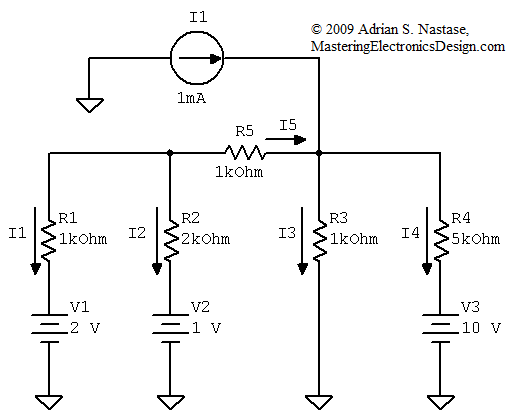
The circuit in Figure 1 has independent sources. This circuit is composed of a mixture of sources, both voltage and current, to make it more challenging. When solving this circuit, we need to use a method to find one, two or all currents flowing through the circuit branches. A brute force approach is to write equations based on Kirchhoff’s circuit laws. Doing so would require 5 equations, 3 loop equations and 2 node equations for 5 unknowns: I1, I2, I3, I4 and I5.

Figure 1
Here comes into play Thevenin’s Theorem. Let’s choose one branch, say the current through R2. For this, let’s redraw the schematic as in Figure 2.

Figure 2
Figure 2 shows that R2 is eliminated and the remaining circuit has an equivalent Thevenin source. The output voltage is noted Voc, as in open circuit voltage. If we know VTH and RTH then, after connecting R2 at this source output, the current flowing through R2 has exactly the same value as in our circuit.
Finding VTH and RTH is easier, because one branch is eliminated. RTH is the resistance seen inside the source, as looking from its output, as in Figure 3. When all voltage sources are short-circuited and current sources are disconnected, all that remains are resistors. Looking from the circuit output, we can see R1 in parallel with R5 which is in series with R3 in parallel with R4.

Figure 3
So, the equation for RTH is as follows,
![]()
where with this symbol || I noted the expression of parallel resistors.
Then RTH is
![]()
Next is the calculation of VTH, which is the same as Voc. To do so, we need the value of I1. Knowing I1, Voc can be calculated from the loop formed by R1, V1, V2 and Voc. There are 2 ways to find R1. One is to use another Thevenin source, which will lead to nested Thevenin sources. You will find this method in the following article How to Apply Thevenin’s Theorem – Part 2. Nested Thevenin Sources Method.
The second method is the use of Kirchhoff’s Laws, only that this time we have just 3 equations, for three unknowns, I1, I3 and I4. You can see the simplification here. We started with 5 equations and we are down to 3.
From Figure 3 we can write the following equations.

After calculations, we find the currents as I1 = 0.176 mA, I3 = ¬2.353 mA, I4 = –1.529 mA. This helps us in finding VTH, by writing the following equation in the Voc loop,
![]()
so VTH = Voc = 1.176 V.
With VTH and RTH known, what’s left is to connect R2 at the Thevenin source output as in Figure 4.

Figure 4
The result is
![]()
To emphasize even more how powerful this method is, let’s assume we need to find out all currents in Figure 1. Instead of writing a system of node and voltage equations, we can take advantage of the current we already know, I2.
I1 is easy to be found from the V1, R1, R2, V2 loop.
![]()
Then I5 = – (I1 + I2) = – 0.332 mA. From V2, R2, R5 and R3 loop, I3 is easily calculated.
![]()
And finally I4, from R3, R4, V3 loop.
![]()
I hope this article convinced you to apply Thevenin’s Theorem more often in your electronics design. The Theorem elegance is another element that makes Electronics Design an art.


What are nested Thevenin sources? You mention this as a second method. Can you please explain?
Part 2 of this series will explain the method. Please RSS this website to be notified when this article will be published.
==============
Update: Part 2 is published here:
How to Apply Thevenin’s Theorem – Part 2, Nested Thevenin Sources Method
First thank you very much…for your contribution and details. I like it.
Few remarks:
1-There is an error-typo when you write “there are two way to find R1” which should read “there are two ways to find I1”
2-Why do you find two different values for each I1, I2, I3 and I4 ? First time you say “After calculation we find… I1 = “0.176 mA”… and later “I1=-0.112 mA” ? Did I get you wrong ?
Brgds
Antonio
Thank you for your comments.
1. I do not see that typo. Maybe you have an old version of this article?
2. As you say in your second post, you found the answer.
Hello Again, I guess I found the answer in your part 2 article
I1 first time is when R2 is out of circuit.. The second I1 is the original I1 of first circuit when the R2 is put back in the circuit.
This is not so clear in the text. Why not to call them I1′ and I1 and I2′ and I2 etc..
Thank you again
Antonio
I see why you would want a different notation for I1. However, I would not change I1 as I change the figure. Although they are different currents, they refer to the same resistor R1. The circuit changes, as the figures show, so the current through R1 changes.