What are Nested Thevenin Sources? I came up with this name recently, while talking to an engineer about a design problem. I just said it, and I liked it. I then went and searched on Internet to see if anybody else used the term Nested Thevenin Sources before. I did not find it so, here it is. Let’s talk about it.
I borrowed the term from “nested loops” in the programming world. The main idea is that you can use a method to accomplish a task inside another method of the same kind, hence the word nested. As we saw in How to Apply Thevenin’s Theorem – Part 1, Thevenin’s Theorem is widely used to simplify the solving of a complex circuit.
With the Nested Thevenin Sources Method you first start to apply this theorem on a complex circuit. The circuit is simplified, but it is still too complex to solve with loop and node equations. Because of that, you apply the theorem again, and you simplify the circuit even more, and so on. At some point, the circuit simplifies so much that, with just a glance, you can tell what is the Thevenin voltage and resistance.
After you find the most inner source Thevenin voltage and resistance, you make your way back and find the currents and voltages up to the highest Thevenin source in the rank.
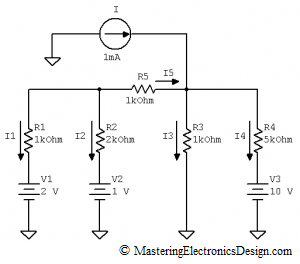
Let’s apply this method on the same circuit I used in Part 1 of this series. The circuit is given in Figure 1. The design asks to find all the currents in the circuit branches. We will choose the same branch as in the previous article, R2 and V2. Being a circuit with independent sources, we can choose any other branch. For a circuit with dependent sources things are different, but we will talk about this in a future article.
Figure 1
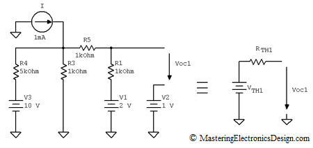
After eliminating R2 from this circuit, the next step is to determine the equivalent Thevenin Source as in Figure 2. VTH1 is the Thevenin voltage of the equivalent source and RTH1 is the resistance.
Figure 2
VTH1 is equal with the open circuit voltage, Voc1, in the simplified circuit. To find Voc1, in the previous article, I applied node and loop equations. This method leads to three equations with three unknowns. However, we can apply again the Thevenin Theorem in this new circuit, to simplify it even more. This will be the Thevenin source number 2, inside the Thevenin Source number 1.
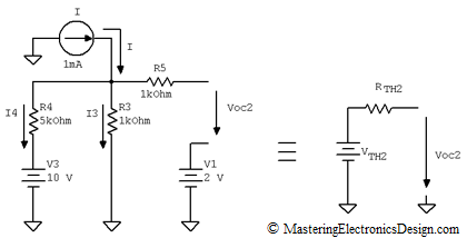
To create the equivalent Thevenin source number 2, let’s remove R1 from this circuit. The new circuit and its equivalent Thevenin source are shown in Figure 3.
Figure 3
This circuit does not need any more simplification. To find Voc2, all we need now is one loop equation for V3, R4, R3, and one node equation for I, I3 and I4.
The result is I3 = 2.5 mA. With I3 known, Voc2 can be easily calculated from Voc2, V1, R3, R5 loop.
and VTH2 = Voc2.
Next is RTH2 which is the output resistance as seen from the Voc2 output. The rule is to consider all the independent voltage sources zero and all the independent current sources disconnected. One can see that the output resistance of the circuit in Figure 3 is R5 in series with the parallel resistors R3 and R4. The mathematical expression is
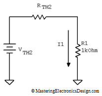
With VTH2 and RTH2 we can calculate I1 through R1 resistor in the circuit in Figure 2. For that, we need to connect R1 to the Thevenin source number 2 we just calculated, as in Figure 4.
Figure 4
This is not the same I1 as in the original circuit in Figure 1, because R2 is missing. However, this I1 will help us find Voc1 which is equal with VTH1.
Since I1 in Figure 2 is known, we can go ahead and calculate Voc1 from the loop made by Voc1, V2, V1, R1.
and VTH1 = Voc1.
RTH1 is the equivalent resistance as seen from the Voc1 output. This was already described in Part 1, so I will just mention here that RTH1 is
or
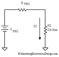
With VTH1 and RTH1 known, we can find I2, in the original circuit in Figure 1. All we have to do is to connect R2 at the Thevenin source VTH1 and RTH1 as in Figure 5.
Figure 5
The result is
which is the same as previously determined in the first part of this series. Once I2 is known, the rest of the currents are easily found. Please go to Part 1 for step by step calculations.





This is such a neat idea. Thank you Adrian.