The transfer function of the differential amplifier, also known as difference amplifier, can be found in articles, websites, formula tables, but where is it coming from? Why is the differential amplifier transfer function as in the following mathematical relation?
| (1) |
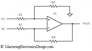
where the resistors are those shown in Figure 1.
First, an important remark: This formula applies only for an ideal operational amplifier. This means that the amplifier has a large gain, so large that it can be considered infinity, and the input offset sufficiently small, so that it can be considered zero. Also, the input bias currents are sufficiently small so that they can be considered zero. I was once asked “but what is sufficiently small?” A voltage or current in electronics is considered sufficiently small, when its numerical value is 1/100 or less versus the dominant voltages or currents in the circuit. For example, if the input voltage levels, in the circuit in Figure 1, are around a few volts, and the operational amplifier input offset is millivolts or sub-millivolts, then we can neglect the input offset and consider it zero.
Having said that, do we need to know this formula by heart? Of course not. All we need to know is how to derive it. This is not difficult at all.
The transfer function can be derived with the help of the Superposition Theorem. This theorem says that the effect of all sources in a linear circuit is the algebraic sum of all of the effects of each source taken separately, in the same circuit. In other words (back at Figure 1), if we remove V1, and replace it with a short circuit to ground and calculate the output voltage, and then we do the same with V2, the output voltage of the differential amplifier is the sum of both output voltages as they were calculated with each source separately.
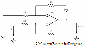
Let’s first remove V1. R1 cannot be left unconnected, because in the initial circuit there was current flowing through it. Therefore, let’s ground R1 (see Figure 2).
We can see that our amplifier becomes an inverter, which has its non-inverting input connected to ground through R1 and R2. Vout2 is given in equation (2).
| (2) |
Read MasteringElectronicsDesign.com: How to Derive the Inverting Amplifier Transfer Function for a proof of this function.
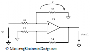
Now let’s remove V2 and ground R3 (see Figure 3).
This is a non-inverting amplifier. For an ideal operational amplifier, Vout1 is a function of V, which is the voltage referred to ground at the non-inverting input of the operational amplifier.
| (3) |
The resistors R1 and R2 are an attenuator for V1, so that V can be determined as in the following relation.
| (4) |
By replacing V in equation (3), Vout1 becomes:
| (5) |
Now that we have Vout1 and Vout2, and using the Superposition Theorem, Vout is the algebraic sum of Vout1 and Vout2,
| (6) |
which is the differential amplifier transfer function. (Q.E.D.)


I searched for how to derive the differential amplifier transfer function with not much hope. I found this very detailed explanation on this website. Thank you so much.
Thanks!
Could you offer the MathCAD files as well? To help us neophytes up and run with amp circuits?
I will create a MathCAD file related to this article. Come back soon.
We could still come to as close to an ideal difference amplifier – that is the difference between the non-inverting input with the inverting input is multiplied by a simple gain G=R4/R3 this is done by design so that R2=R4 and R1=R3 then the entire derived equation reduces to Vout=DeltaVin*G=(V1-V2)*(R4/R3)
Correct for R2=R4 and R1=R3. Still, this is just one case. This article shows the derivation of the general form of the transfer function because it can be used to build other circuits, not only a simple difference. For example, one can design a unipolar to bipolar converter as in this article I published some time ago: Design a Unipolar to Bipolar Converter for a Unipolar Voltage Output DAC. Thank you for your comment.
Many thanks
Where can I find how to derive the bandpass filter and band reject filter transfer function?
If you perform some broad search on internet, you should find some info. Also, Wikipedia is a good source for filters.
Manufacturers like Texas Instruments, Linear Technology and Analog Devices have good articles about filters as well. Do a search on their websites.
Other than that, try to find some textbooks that describe the filters.
Sometime in the future I will write a series about filters.
many many thanx
Thanks for explanation……………
Thanks alot, you explained better than my lectuer.
What can I do to make the transfer function in terms of vin?
Simply replace V1 with Vin.