One of my readers posted the following questions in the comment section of MasteringElectronicsDesign.com: An Op Amp Gain Bandwidth Product.
I am doing a work on fully differential Negative feedback op-amp with capacitive divider configuration. I have some questions and confusions, can you please clarify?
What is the difference between closed loop gain and open loop gain, and are they dependent to each other?
How can we calculate the unity gain frequency if I have a 3-dB frequency of 100Hz and closed loop gain of 40dB?
Does the feedback factor (BETA) has importance with respect to any other parameters?
How will it help in finding the closed transfer function of the system assuming the op-amp as a single pole system?
The answers needed some space, more than the comment section could offer, so here is a post on the topics of op amp open-loop, closed-loop and feedback.
Q1: What is the difference between closed loop gain and open loop gain, and are they dependent to each other?
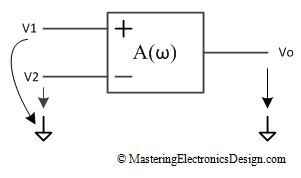
A1: In general terms, an amplifier has gain, which represents the ratio between the output signal amplitude versus the input signal amplitude. If the gain is frequency dependent, we note it with A(ω) to show that dependence. Figure 1 shows the amplifier, represented as a black-box, with two input signals, V1 and V2, and an output signal Vo. The signals are shown with respect to ground.
This is the basic op amp. The output Vo depends on the difference between the two inputs as follows:
| (1) |
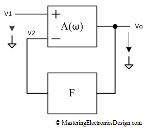
If we bring negative feedback from output to input around this amplifier, in other words, close the loop, the entire system gain changes and its value depends on feedback. As such, we call A(ω) open-loop gain, and the gain of the op amp with negative feedback, closed-loop gain, noted ACL(ω). Figure 2 shows the block diagram of an amplifier with negative feedback, where the F box shows the feedback network.
When the loop is closed, equation (1) becomes
| (2) |
F is called the feedback coefficient. ACL(ω) depends on A(ω) with the following formula:
| (3) |
Of course, F can be dependent on frequency as well, but I want to keep this simple for now.
Note: If you want to know how this formula can be derived, here are a few quick steps:
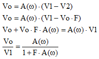 |
(4) |
Q2: How can we calculate the unity gain frequency if I have a 3-dB frequency of 100Hz and closed loop gain of 40dB?
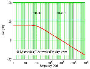
A2: Compensated op amps have one pole. The gain drops at 20 dB per decade after that pole. (see Figure 3).
In a closed loop system, the gain is set by the feedback network, provided that the open loop gain is high (see answer 3 as well). No matter the closed loop gain level, the product between gain and bandwidth, or the gain bandwidth product (GBW) is constant. Therefore, the GBW in this case is
| (5) |
We can apply this value to calculate the unity gain frequency:
| (6) |
Q3: Does the feedback factor (BETA) has importance with respect to any other parameters?
A3: Yes it does. The first answer shows that the feedback factor is used in the closed loop gain calculation. Also, if the open loop gain is high, the feedback factor determines the closed loop gain at DC and in band. Indeed, let’s show this by rewriting equation (3) at DC.
| (7) |
where with ACLO I noted the closed loop gain and with Ao the open loop gain, both at DC. If Ao is high enough so that 1 in the denominator can be neglected, ACLO becomes
| (8) |
Besides determining the gain, if F depends on frequency, it will also modify the amplifier bandwidth. Active analog filters can be designed by simply designing the correct feedback network.
Q4: How will it help in finding the closed transfer function of the system assuming the op-amp as a single pole system?
A4: The answer to this question is given by equation (3). Assuming that the feedback coefficient is not frequency dependent, the closed loop transfer function is
| (9) |
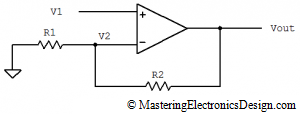
If the network feedback is made with two resistors, as in the non-inverting amplifier shown in Figure 4,
The transfer function becomes
 |
(10) |
An operational amplifier open loop gain can be written as
 |
(11) |
where with Ao I noted the op amp open loop gain at DC and with ωo the op amp cutoff frequency in radians per second.
Replacing (11) in (10), and after calculations, the closed-loop gain becomes
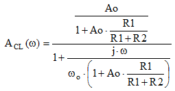 |
(12) |
Based on (7), the closed-loop gain or transfer function can be written as
 |
(13) |
where with ωCLO I noted the cutoff frequency in closed loop, in radians per second.
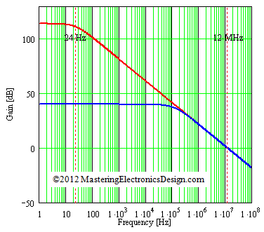
It should be clear now that the feedback coefficient modifies both the amplifier gain and bandwidth. The following figure shows an example. ADA4004 open-loop gain starts rolling off at 24Hz. The red trace shows the open-loop gain. If we close the loop as in Figure 4, with R1 = 100 koms and R2 = 1 kohm, the new transfer function is represented by the blue trace which is a plot of the transfer function shown in (13).




Thank you very much. I learnt a lot.
And could you make a topic about oscillator and stability criteria?
i want exercises of open loop gain ??
Sorry, cannot help you with that. You need to find a textbook that also has some examples/exercises.
thanks for the article, I have a question if the closed loop gain is
(ks+a)/(s^2 +as+b)
can we just say that the open loop gain is s^2+as+b-1?
Nope. You need to bring this transfer function in textbook form: A(s)/(A(s)H(s)+1). A(s)H(s) in this expression is the feedback. If this is difficult to solve, go back to your schematic, open the loop, and calculate the gain. That is the open-loop gain you’re looking for.
how to calculate the open loop gain?
I need drawings and equations to show you how, so I will write an article on this subject.
how the variation of loop gain effects voltages and currents in opamp.
It affects the output signal amplitude and the circuit bandwidth. It all depends on the circuit. For more specifics you need to show me the circuit you are talking about.
I have doubt in a quest could you help me ?
Quest:-
The open-loop DC gain of a unity negative feedback system with closed-loop transfer function is
s+4/(s^2+7s+13)
Your forgot the parenthesis around the numerator. I believe your closed-loop transfer function is (s+4)/(s^2+7s+13) This looks like homework so I am not going to solve it for you. I can give you a hint though, so that you can do it yourself. The closed-loop transfer function is A(s)/(A(s)H(s)+1). H(s) in this expression is the feedback transfer function and A(s)H(s) is the open-loop. So, obviously A(s) is the numerator of your function. Now you have to find H(s) in the denominator.
In op-amp what is output driving capability,how should we calculate the output driving capability of the op-amp?
You do not calculate it. You look it up in the op amp specs. The output driving capability is the op amp maximum output current.
for the two stage opamp with cap as load,So i need to check what is the maximum output current across the cap while maintaing slew rate and maintaing saturation region in all mosfets?
whether it has to check in unity gain configuration or different one?can u please specify
The configuration does not matter. The maximum current capability of the op amp is what limits the capacitor current charge.
significance of open loop gain closed loop gain of opamp
sorry i mean
significance of relation of open loop and close loop gain….?
This sounds like the first question in this article. My answer shows the relation between open-loop and closed-loop.
Dear Adrian,
my question is not on feedback but on cross over frequency.I am stuck with a problem that is really getting on my nerves because i can’t solve it.It is really frustrating and i have no professional around me to turn to.I tried hard though going thru phase angles and polar equations but to no avail.The data for the response curve is given below.
Aol gain=8odB,-3dB gain=0.7Mhz,64dB=3Mhz,33dB=18Mhz.
The question is to calculate the crossover frequency and the book’s answer is 72.3Mhz..I didn’t come even close to that answerAnyway how is the gain 64 and 33dB at 3Mhz and 18 Mhz respectively? Please can you help ? you will make me a happy apprentice again.thanks.
Eric, this sounds like homework, so all I can do for you is to tell you how to approach this problem, not to solve it for you. You need to solve it yourself.
First of all, you should verify the drop rate between each frequency. Simply calculate the slope. I calculated that between 0.7 MHz and 3 MHz you have 20 dB/decade, and between 3 MHz and 18 MHz there is 40 dB/decade. You need to prove that before going further. Therefore, the transfer function is a multiplication of 3 first-order one pole transfer functions like this:
TF(f) = Gain * (1/(1+i f/f0)) * (1/(1+i f/f1)) * (1/(1+i f/f0))
where Gain = 10^4 (or 80 dB), f0 = 0.7 MHz, f1 = 3 MHz, f2 = 18 MHz
From here you have three methods to find the cross-over frequency:
1. Graphical solution: You can use a program like Mathcad or Matlab to draw the graph of |TF(f)|and then check at what frequency it crosses over.
2. Equation solving: Make |TF(f)| = 1 and again use Mathcad to solve this equation in f.
3. Asymptote approximation: Use the asymptotes to determine at what fraction of the decade between 18 MHz and 180 MHz is the cross-over frequency. Using the graph linearization with asymptotes, will give you an approximate frequency. Here is how:
After 18 MHz the drop is 60 dB/decade. Doing a quick calculation I got that the cross over frequency falls at 0.6 of the decade between 18 MHz and 180 MHz. This value is calculated with the 60dB/decade slope and the 3dB correction at 18 MHz. In other words, you consider 36 dB at 18 MHz not 33 dB. To calculate the frequency you apply to 0.6 the inverse of logarithm in 10, multiplied by 18 MHz. I calculated 71.65 MHz, very close to the book result.
Thanks for the explanation.
Hi Eric,
That is really helpful. I wonder in Fig. 5 the 2 resistors should be 100ohm and 10kohm right?
In Fig 5 the graph shows and amplifier with the two resistors 100kohm and 1kohm but, indeed, they can be 10kohm and 100ohm.
Thanks for the informative blog
This was the most helpful content for the loop gain and stuff. Love your site. <3
Glad to hear that.