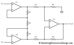
The Instrumentation Amplifier (IA) resembles the differential amplifier, with the main difference that the inputs are buffered by two Op Amps. Besides that, it is designed for low DC offset, low offset drift with temperature, low input bias currents and high common-mode rejection ratio. These qualities make the IA very useful in analog circuit design, in precision applications and in sensor signal processing.
Figure 1
Figure 1 shows one of the most common configurations of the instrumentation amplifier. Its clever design allows U1 and U2 operational amplifiers to share the current through the feedback resistors R5, R6 and RG. Because of that, one single resistor change, RG, changes the instrumentation amplifier gain, as we will see further. RG is called the “gain resistor”. If the amplifier is integrated on a single monolithic chip, RG is usually left outside so that the user can change the gain as he wishes. One example of such instrumentation amplifier is Texas Instruments’ INA128/INA129.


