In a previous article, How to Derive the Summing Amplifier Transfer Function, I deduced the formula for the non-inverting summing amplifier with two signals in its input. But what if we have 3, 4 or an n number of signals? Can we add them all with one amplifier?
Theoretically, yes. Practically, it is a different story. There is a practical limit on how many signals can be summed up with one amplifier. When the number of input signals grows, each signal component in the sum decreases in value. By the end of this article you will understand why.
Figure 1
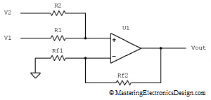
We already saw that, for a summing amplifier with two input signals (Figure 1), the transfer function is
| (1) |
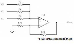
If we need to add 3 signals, the circuit schematic looks like the one in Figure 2. What is the transfer function of this summing amplifier with 3 inputs?
Figure 2
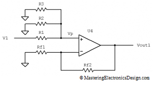
Using the Superposition Theorem, we will first leave just V1 in this circuit. V2 and V3 are made zero, by connecting R2 and R3 to ground (Figure 3).
Figure 3
For an ideal Op Amp, we can consider that the input current in the non-inverting input is zero. With this assumption in mind, resistors R1, R2 and R3 make a voltage attenuator, with R2 and R3 in parallel. Therefore Vp is
| (2) |
where with R2 || R3 I noted the parallel value of R2 and R3.
With just the input source V1, the Op Amp output is noted with Vout1 and can be written as
| (3) |
or, after replacing Vp with expression (2),
| (4) |
Similarly, we can write Vout2 and Vout3 when the only input signals are V2 and V3 respectively.
| (5) |
| (6) |
Adding equations (4), (5), and (6) as the Superposition Theorem says, the transfer function of a non-inverting summing amplifier with 3 input signals becomes:
 |
(7) |
Now, I have to replace the parallel symbol || with the actual mathematical expression. For simplicity (at least this is how it looks to me), I will use the power of negative one rather than fractions. Therefore Vout is
 |
(8) |
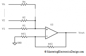
What about a summing amplifier with 4 inputs or with 5? Better, let’s derive the summing amplifier transfer function for n inputs (Figure 4). That way, one can use this formula in a simulation program or a math program like Mathcad to determine the output level for a certain pattern of signals in the amplifier input.
I will use equation (8) to derive the transfer function for n inputs. Equation (8) can be written in a more convenient way, more compact, so that the n inputs will become evident.
Figure 4
We can see that, in the first term, V1 multiplies a fraction that can be written as in (9).
 |
(9) |
where k counts the number of input resistors.
With this notation, the transfer function of the summing amplifier with 3 inputs becomes
 |
(10) |
or, simplified,
 |
(11) |
and where j counts the number of signals.
Equation (11) can be easily expended to n input signals. All we have to do now is to replace the number 3 with n.
Therefore, the transfer function of the summing amplifier with n input signals becomes:
 |
(12) |
Q. E. D.
>>> <<<
It is easy to see that, as the number of input signals increases, the parentheses’ value decreases (they are at the power of negative one), so the fraction decreases. As a consequence, as the number of input signals increases, each sum component decreases. The input signals’ weight in the sum can become very small and approach the noise floor in the system. As we will see in a future article, the inverting summing amplifier is better fit for a large number of input signals.
Still, deriving the summing amplifier transfer function with n inputs is fun, isn’t it?


oh man. and fun it is. took me awhile but i finally got it. thanks for this great article.
Very interesting the proof of this transfer function. A summing amplifier with multiple input signals can be useful in many applications. You can create an Excel spreadsheet and plug in voltage levels and play with the resistors values until you get it right.
Thanks for a job well done.
Matt
If you have n input signals in the summing amplifier, what happens with the resistive imbalance between the 2 inputs of the op amp? How do you match the input resistance for each input? And is it necessary?
Yes, you need to match the total value of the resistors in the non-inverting input with those in the inverting input. The input bias currents will generate a voltage drop on these resistors. If the total resistor values are not equal, the voltage drop will generate an offset error, which will be multiplied by the total gain of the amplifier.
For the summing amplifier with n input signals you need to make sure that
R1 || R2 || … || Rn = Rf1 || Rf2.
Easier said than done, but doable. At minimum, try to bring them as close as possible, or use an Op Amp with low input currents.
Adrian,
Glad I stopped by today. Thanks for letting me know about your blog. I very much appreciate rigor and mathematical derivations. This to me forms an “intuitive” approach to analog design/analysis, but is probably the reason why it took me so long to finish my thesis (!).
Instead of building a summing amplifier we just bought a multiplexed DMM/DAQ unit from Keithley, and I might end up connecting each probe to a separate channel and averaging the individual readings. My experience with analog or digital electronics is it helps to have a tech around to build the stuff.
Cheers. Excellent website!
Matt O’D
Thanks Matt. I appreciate that.
Thank you very much for this article! greatly improved my understanding. Very detailed explanation and diagrams. Thanks again 🙂
Hi Andrew, I’m glad you found it useful. Thanks for stopping by.
What a nice website!
Thank you very much for this all.
It’s very very the best…
Thank you. Please click the like button.
The detailed expression of the N-input case is close to intractable. It is almost impossible to see the essential dependencies.
However, the special case where all input resistors Ri are equal is A LOT simpler to calculate, and appears to give the result, for V1 only, Vp=V1/N. Hence, Vp=sum(Vi/N)=1/N * Sum(Vi). Effectively, the input to non-inverting summing amplifier reduces to *the average* of input signals.
Intractable? Maybe. As with anything involving math, for some people will be easy for some other will be difficult. Take a look at Matt’s comment above. He proposes a spreadsheet to play with values. I can also tell you that a Mathcad file will also make it easy. I wrote the N input article to have fun with it and to show people that it is possible to find a general formula. I did not find this anywhere else.
For 2, 3, or 4 inputs this is really easy. I used this circuit many times in my career to mix signals, each one at a different amplitude level. You are right that if all resistors are equal you get the signals’ average. I described it in this article, MasteringElectronicsDesign.com: Using the Summing Amplifier as an Average Amplifier. However, this is not the only application. A more important application is creating a weight function where some inputs have more weight than others and this is what this article is about.
Adrian,
Nice article, I like how you use superposition. The essential dependencies can be made clearer if you rewrite the formulas somewhat. In particular, your equation (1) can be written as
Vout = (1 + Rf2/Rf1) . (V1 . 1/R1 + V2 . 1/R2) . R1||R2
Likewise, for 3 inputs, equation (8) can with a little work be rewritten as
Vout = (1 + Rf2/Rf1) . (V1 . 1/R1 + V2 . 1/R2 + V3 . 1/R3) . R1||R2||R3
and for n inputs (I hope the alignment shows as intended)
n n
Vout = (1 + Rf2/Rf1) . Sigma(Vj . 1/Rj) / Sigma(1/Rj)
j=1 j=1
I feel this form better reflects the application of this circuit as weighted sum, where the weight of each input is simply the conductance if its input resistor divided by the total conductance of all input resistors.
Rgds, Hans
Thank you, Hans, for your comment. Your form shows the sum of currents in the non-inverting input, multiplied by the equivalent resistance of all the resistors in the same input. I see that it renders a different view of how the circuit works, especially for the N inputs. I will think of a way to include this in the article.
thak you very much
I’m glad you found it useful.
You write: “If your goal is unity gain, then you’re just wasting an op-amp.”
That is incorrect. You might need a buffer.