Why is the Op Amp Gain-Bandwidth Product Constant?

A recurring conversation I have usually starts with two questions: Why is the op amp gain-bandwidth product constant? And, how can we prove that?

The questions refer to the gain-bandwidth product behavior of an op amp after the cutoff frequency. As I showed in this article, MasteringElectronicsDesign.com: An Op Amp Gain Bandwidth Product, the gain bandwidth product describes the op amp gain dependency on frequency. The open loop graph is shown in Figure 1.

Read more

Open-loop, Closed-loop and Feedback Questions and Answers

One of my readers posted the following questions in the comment section of MasteringElectronicsDesign.com: An Op Amp Gain Bandwidth Product.

I am doing a work on fully differential Negative feedback op-amp with capacitive divider configuration. I have some questions and confusions, can you please clarify?

What is the difference between closed loop gain and open loop gain, and are they dependent to each other?

How can we calculate the unity gain frequency if I have a 3-dB frequency of 100Hz and closed loop gain of 40dB?

Does the feedback factor (BETA) has importance with respect to any other parameters?

How will it help in finding the closed transfer function of the system assuming the op-amp as a single pole system?

The answers needed some space, more than the comment section could offer, so here is a post on the topics of op amp open-loop, closed-loop and feedback.

Read more

Measure a Bipolar Signal with an Arduino Board

Arduino is a popular family of open source microcontroller boards. Hobbyists, students and engineers all over the world use this platform to quickly design and prototype a microcontroller driven circuit. One of its interfaces with the analog world is the ADC. Since these boards are mostly designed around an ATMEL ATmega32 or ATmega168 microcontroller, the ADC has 8 inputs and 10-bit resolution, making it suitable for many applications.

From time to time I receive a message through my Contact page with the question, how to interface a sensor, or an outside circuit with the Arduino ADC? In most cases the answer is an interface between a bipolar circuit and the Arduino board. As the bipolar circuit output varies from some negative to a positive level, the Arduino ADC cannot measure this signal directly, because the ADC inputs can only be between 0V and the reference voltage.

In one of these messages a reader asked me how to build an interface between a board that has an output voltage of -2.5V to +2.5V and the Arduino ADC. He told me that the Arduino reference voltage is AVCC = 5V. He would like to measure the +/-2.5V signal with the Arduino board and direct the microcontroller to take some action based on the result.

Read more

Apply Thevenin’s Theorem to Solve a Negative Resistance Circuit, or Current Source

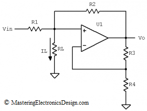
The circuit in Figure 1 is a good example of applying Thevenin’s Theorem to solve a circuit with dependent supplies. It is a negative resistance circuit and it was posted in this forum with a call for solution verification for IL as a function of Vin. With some clever resistor values, the circuit can also be a current source with RL its load. Since this fits very well with my plans to write more about Thevenin’s Theorem, I decided to post the solution here.

negative-resistance-circuit

Figure 1

Read more

Build an Op Amp SPICE Model from Its Datasheet – Part 3

MasteringElectronicsDesign.com:Build an Op Amp SPICE Model from Its Datasheet – Part 1 and Part 2 show you how to build an Op Amp SPICE model based on the manufacturer’s datasheet. We talked about modeling the offset voltage, the input resistance and capacitance both common-mode and differential, the output resistance and the frequency domain behavior.

In Part 2, we left off at the open-loop bode plot. We saw that it resembles the datasheet. However, our op amp example, ADA4004 from Analog Devices, shows an extra pole after 1 MHz. Indeed, the phase starts dropping after 1 MHz and becomes 45 degrees at 17 MHz. Therefore, we need another pole in our model at 17 MHz.

Introducing the Second Pole

The pole can be introduced using the same technique we used in Part 2. We will use an RC Norton source. Since the DC open-loop gain is already set by the first pole, we only need to make sure that the choice of current and resistor does not affect the DC gain. This second pole influence has to be only at high frequencies. At low frequencies its gain should be 1, so that the overall open-loop gain remains 500000.

Read more

Build an Op Amp SPICE Model from Its Datasheet – Part 2

Part 1 of this article (http://MasteringElectronicsDesign.com/buildi-an-op-amp-spice-model-from-its-datasheet/) shows how to create a behavioral model of an operational amplifier based on the following parameters found in the datasheet: Input and output resistance, input capacitance, DC gain, and offset voltage. As an example I chose Analog Devices’ ADA4004. Let’s continue building this model to simulate the Gain Bandwidth Product.

Gain Bandwidth Product

The Gain Bandwidth Product, describes the op amp behavior with frequency. Op amps have a dominant pole, inserted by manufacturers on purpose, so that the op amp is stable at any gain down to zero dB. See this article for more details: MasteringElectronicsDesign.com:An Op Amp Gain Bandwidth Product. In that article I showed that ADA4004 has a cutoff frequency at 24 Hz. This frequency is not identified in the datasheet, but can be easily calculated from the open-loop minimum gain of 500000 and the gain bandwidth product of 12 MHz.

Starting with the cut-off frequency, the open loop gain versus frequency plot has a drop of 20dB for every decade of frequency. To simulate this we need to introduce this pole in our SPICE model. Question is, how?

Read more

An Op Amp Gain Bandwidth Product

I can see some chat on internet about the operational amplifier gain bandwidth product. People are interested in having a better understanding of this parameter, as it appears in any op amp datasheet and it is used in many articles and books. In this article I will describe this parameter and show you an example with Analog Devices’ ADA4004, which is a precision amplifier.

The Gain Bandwidth Product describes the op amp gain behavior with frequency. Manufacturers insert a dominant pole in the op amp frequency response, so that the output voltage versus frequency is predictable. Why do they do that? Because the operational amplifier, which is grown on a silicon die, has many active components, each one with its own cutoff frequency and frequency response. Because of that, the operational amplifier frequency response would be random, with poles and zeros which would differ from op amp to op amp even in the same family. As a consequence, manufacturers thought of introducing a dominant pole in the schematic, so that the op amp response becomes more predictable. It is a way of “standardizing” the op amp frequency response. At the same time, it makes the op amp more user friendly, because its stability in a schematic becomes more predictable.

Read more

Show Buttons
Hide Buttons
'