You worked hard on your schematic, you calculated everything, you feel confident that it will work. To be sure though, before committing the schematic to copper, you want to simulate it. You develop a SPICE simulation schematic and, surprise, things don’t work. What’s going on?
You start searching for bad connections in the simulation schematic. You check the power supplies and the circuit biasing. Finally, in desperation, you suspect the operational amplifier model that you downloaded from the manufacturer website, or found in the SPICE program library. How do you troubleshoot your circuit?
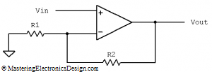
First, split your circuit into small subcircuits, like a one op amp circuit. Second, take aside, on a different simulation page, one of these subcircuits. Is that working? If that circuit is a non-inverting amplifier, as an example (Figure 1), and the output voltage is all over the place except your expected value, than replace your op amp with an ideal one and see if that circuit works.
And so we come to the main idea of this article. What is an ideal op amp? Well, any electrical engineering student will tell you that, an ideal op amp has a large DC gain, a large input impedance, zero output impedance, no voltage or current offset, zero bias currents, large slew rate, huge bandwidth, large output voltage swing. When we talk about “large” and “huge”, the numbers attached to these parameters approach infinity by math standards. However, in electronics, we consider a DC gain to be huge if it is over 120 dB (or 1 million), an impedance is large if it is 1 Gohm, output voltage swing is large if it goes to 100 V, etc.
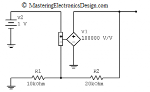
What op amp should we use in SPICE for troubleshooting purposes? Just use a Voltage-Controlled-Voltage-Source (VCVS), and set its gain at something above 100,000. The following image shows a VCVS used in a non-inverting amplifier configuration in Multisim(1).
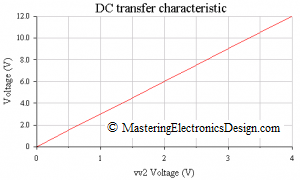
You can DC sweep the input of the non-inverting amplifier to find out the output response. The following figure shows a graph of output versus input for the schematic in Figure 2. One can see that our ideal op amp works as expected.
Such method can give us some confidence if the schematic we developed has any chances to work. If it works with this perfect op amp, and does not work with the op amp model we were tying to use, than there is something wrong with the op amp model, its polarity, pin connections, etc.
If this method tells us that we have a broken op amp model, the next step is to find a good working one, or develop our own from the op amp data sheet. But, we will talk about this in a future article. Stay tuned. Use the RSS feed or the Facebook link.
======
(1) Multisim is an electronic simulation program by Electronics Workbench, which is now a division of National Instruments.


Hi Adrian,
may I suggest something to you?
For my opinion, it would be a good idea to create a new “category” called “circuit simulation” in which some specific simulation problems are presented resp. discussed (errors, misinterpretations of simulation results).
For example: What happens when unintentionally the resistive feedback of an opamp is connected to the non-inverting input? I am afraid, the program will compute a stable bias point – and very often the user will not detect his error. Even the ac analysis will give a reasonable magnitude response.
Some other points of interest could be (a) the meaning of the feature “cancel initial bias point” and (b) the reason for convergence problems (and what to do against it) or (c) some hints for correct loop gain simulation (phase margin of a control system with feedback).
Regards
Lutz
Hi Lutz, thank you for this idea. I plan to write more about circuit simulation, so yes, these articles can be posted under such a category.