One of my readers asked me to explain how I designed a circuit I posted in a forum, as a solution to one of the member’s question. The problem was about designing a circuit with 3 input signals, VA, VB and VCM. The circuit had to output the sum and difference between VCM and the average of VA and VB as in the following expressions:
 |
(1) |
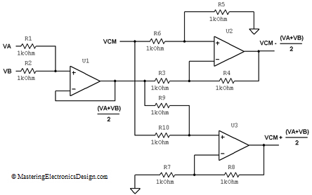
The solution I posted is the circuit in Figure 1.
Figure 1
What is the easiest way to design this circuit?
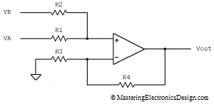
The first thing we note in equation (1) is that VA and VB are summed and then divided by two. This is the average of VA and VB, and the non-inverting summing amplifier can do this easily. As we saw in Solving the Summing Amplifier, the circuit in Figure 2, the non-inverting summing amplifier, has the following transfer function:
| (2) |
We can follow the steps I described in Solving the Summing Amplifier to design the resistors, but this is a simple circuit. In order to obtain the function (VA+VB)/2 both fractions in equation (2), R2/(R1+R2) and R1/(R1+R2), have to be equal and equal to 1/2. This can happen only if R1 = R2. For this circuit I chose 1 kohm resistors, but the resistor’s value can be anything as long as we do not choose ridiculously low or ridiculously high resistors. Since the first parenthesis solves this average, the second one has to be equal with one. Therefore, R4 is zero (just a wire) and R3 is infinity (disconnected).
Next, we need to create the function VCM + (VA+VB)/2. It is clear that we need a summing amplifier as well so equation (2) helps to achieve this function. U3 in Figure 1 does this for us. Based on equation (2), its output signal can be written as
| (3) |
With R9 and R10 equal, the first parenthesis becomes [VCM + (VA+VB)/2]/2 so we need the second parenthesis to be 2. Therefore, R7 = R8 = 1 kohm and R9 = R10 = 1 kohm.
Moving on to the second output, we need a difference circuit. U2 in Figure 1 is a differential amplifier with the transfer function as in equation (4). (Details about this circuit can be found in The Differential Amplifier Transfer Function.)
| (4) |
If all the resistors are equal, this circuit simply outputs the difference VCM – (VA+VB)/2. Hence, R3 = R4 = R5 = R6 = 1kohm.
What is this circuit good for?
It creates a single-ended-input-differential-output amplifier, in which VCM is the common mode and the main signal, in this case the average (VA+VB)/2 rides on top of VCM. It is very useful for fully differential circuits in low noise applications, because differential amplifiers help reduce the common mode noise. VCM in this case, sets the common mode to a useful level as required by the design.


