My Interview in EEWeb

I was recently interviewed by EEWeb for the Featured Engineer edition. EEWeb, an electrical engineering publication, has many remarkable sections, including Analog Design, RF Design, tools, jobs, projects, and even a comic section. Of interest is the EEWeb forum, which is a growing discussion board organized in categories.

Here is an excerpt from the interview:

Read more

Become a Mentor

For a few years now I mentor students at Ocean View High School in Huntington Beach, California. My activity is part of a program called Business Academy developed at Ocean High in the last years. Every spring, students meet accomplished professionals and business people who become their mentors. The goal of the program is to teach and show students the path to a professional life and what to do to pursue their goals.

Read more

Measure a Bipolar Signal with an Arduino Board

Arduino is a popular family of open source microcontroller boards. Hobbyists, students and engineers all over the world use this platform to quickly design and prototype a microcontroller driven circuit. One of its interfaces with the analog world is the ADC. Since these boards are mostly designed around an ATMEL ATmega32 or ATmega168 microcontroller, the ADC has 8 inputs and 10-bit resolution, making it suitable for many applications.

From time to time I receive a message through my Contact page with the question, how to interface a sensor, or an outside circuit with the Arduino ADC? In most cases the answer is an interface between a bipolar circuit and the Arduino board. As the bipolar circuit output varies from some negative to a positive level, the Arduino ADC cannot measure this signal directly, because the ADC inputs can only be between 0V and the reference voltage.

In one of these messages a reader asked me how to build an interface between a board that has an output voltage of -2.5V to +2.5V and the Arduino ADC. He told me that the Arduino reference voltage is AVCC = 5V. He would like to measure the +/-2.5V signal with the Arduino board and direct the microcontroller to take some action based on the result.

Read more

Measure a Wheatstone Bridge Sensor Signal with an ADC

I received a message from one of my readers asking me to help with a Wheatstone bridge circuit. Since my response to him bounced back, and this being an interesting subject, I decided to write this article. Here is what he writes:

I found a circuit to condition the output of the Wheatstone bridge in the National ADC1205 datasheet, page 16. It uses an Op Amp configured as follows: V1 from the bridge thru 10K resistor to (–) input of Op Amp, 1.5Meg feedback resistor and Vout connects to the V- of the 5V ADC. V2 from the bridge connects directly to (+) input of the op amp and the V+ of the ADC.

The bridge V2-V1 is 0 mV to 30 mV. This is both at 5.000 V (0 mV) and V1 = 4.985 V, V2 = 5.015 V (30 mV). Please advise the equations to calculate how this works. Since the ADC is 5 V, I cannot see how the Vout can exceed that voltage. Is it true that Vout = 5.015 V when V1 = V2 = 5.015 V and ADC Out = 0 V?

The National ADC1205 is an obsolete component now, but the advice and application notes are still valid. We can use any ADC if we can correctly adjust Vref and the operating conditions. We can use an Arduino board as well, with its 10-bit ADC to achieve a complete system.

Read more

Come to My Electronics Class on June 9th, at UCR

Every summer Mt. San Jacinto College has a program called STEM (Science, Technology, Engineering and Math). This year, the event will be on June 6 – 9 at Mt. San Jacinto College campus and also at University of California Riverside. Students in the Riverside district are invited to participate, and explore the program classes. The event is intended to expose students to science and technology and help them get more clarity in choosing their future profession.

Read more

Apply Thevenin’s Theorem to Solve a Negative Resistance Circuit, or Current Source

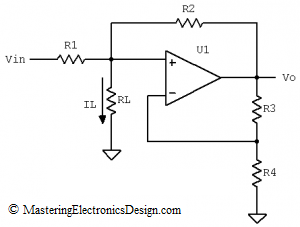
The circuit in Figure 1 is a good example of applying Thevenin’s Theorem to solve a circuit with dependent supplies. It is a negative resistance circuit and it was posted in this forum with a call for solution verification for IL as a function of Vin. With some clever resistor values, the circuit can also be a current source with RL its load. Since this fits very well with my plans to write more about Thevenin’s Theorem, I decided to post the solution here.

negative-resistance-circuit

Figure 1

Read more

Build an Op Amp SPICE Model from Its Datasheet – Part 4

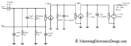
MasteringElectronicsDesign.com:Build an Op Amp SPICE Model from Its Datasheet – Part 1, Part 2, and Part 3 of this article show how to create a behavioral model of an operational amplifier based on the following parameters found in the datasheet: Input and output resistance, input capacitance, DC gain, offset voltage and gain bandwidth product. As an example I chose Analog Devices’ ADA4004 and built its behavioral model step by step. Figure 1 shows the model as we left off at the end of part 3.

ADA4004 macro model with two polesExpand this figure

Figure 1

Let’s continue building this model with some more parameters.

Read more

Show Buttons
Hide Buttons
'