Design a Differential Amplifier with the Coefficients Identification Method
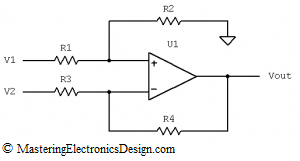
In the first part of this series, MasteringElectronicsDesign.com: Solving the Differential Amplifier – Part 1, I wrote that the common usage of the differential amplifier is as a gain circuit for the differential voltage at its inputs. When the circuit in Figure 1 has the resistor ratios equal
| (1) |
the amplifier transfer function is
| (2) |
and the circuit amplifies the difference between the input signals.
Figure 1
But the resistors’ calculation becomes a bit of a challenge, when one might be faced with designing a differential amplifier with a certain transfer function. The example I took in the first article was as follows: Given an input range of, -0.5V to 5.5V, the output has to swing between, -1.25V and +2.365V. I solved the problem by using the amplifier transfer function and a system of equations.
In this article I am going to write about designing the resistors of this differential amplifier using the method of coefficients identification.
Starting from the differential amplifier transfer function,
| (3) |
we note that this is a linear function Vo, with two variables: V1 and V2. However, if we consider one of these two variables a known value, say, V2, Vo becomes a simple linear function with one variable. Let’s note this function with Vo(V1).
The design requirements are as follows:
If Vin1 = -0.5V, then Vout1 = -1.25V and
If Vin2 = 5.5V, then Vout2 = 2.365V,
where by Vin1 and Vin2 I noted the input range limits, and by Vout1 and Vout2 I noted the output range limits.
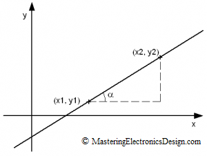
A linear function of first degree is a straight line which is determined by two points in the (x,y) plane (see Figure 2).
Figure 2
If we know one point (x1,y1) and the second point (x2,y2), we can determine the slope of the line, which is the tangent of the angle α between the x2-x1 and the hypotenuse of the triangle formed by the segments x2-x1 and y2-y1.
| (4) |
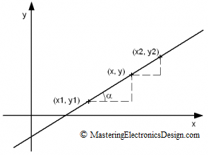
If we take an arbitrary point on this line between (x1,y1) and (x2,y2) and call it (x,y), the slope of the line has to be the same between the segment to the left and the one to the right of (x,y) point (see Figure 3).
| (5) |
Figure 3
Solving for y in equation (5), the result the well known linear function y(x), that we know it goes through the first point (x1,y1) and the second point (x2,y2).
| (6) |
Having said that, now we can compare the differential amplifier transfer function (3) with the linear function (6). When these two functions are identical, Vo(V1) is y(x) and V1 is the variable x. These are two linear functions that can be identical only if they have the coefficients identical, hence the name of the method.
 |
(7) |
As y(x) is determined by its two points in plan, so is Vo(V1). The given data points (Vin1, Vo1) and (Vin2, Vo2) determine the transfer function Vo(V1). Therefore, (7) can be rewritten as the following system of equations.
 |
(8) |
After replacing the known values Vin1, Vin2, Vout1 and Vout2 and after calculations, the system becomes
 |
(9) |
which is exactly the result we had in part one of this series.
The system of equations (9) can be solved in the same manner as in the first article. In brief, we choose the voltage reference V2, based on the available voltage references we have in the system, then we calculate the ratio . Knowing this ratio we can calculate. Then, knowing the resistor ratios, by choosing a pair of resistors say, R1 and R3 we can calculate R2 and R4.
Therefore, if we choose V2 = 2.5V, R3 = 10 kOhm, and R1 = 10 kOhm, the result is R4 = 3.795 kOhm, or a standard value of 3.83 kOhm, with 1% tolerance. Also, R2 = 7.754 kOhm, or a standard value of 7.68 kOhm, with 1% tolerance.


