Design a Unipolar to Bipolar Converter the Easy Way with Microsoft Mathematics

Many analog circuits can be calculated with simple algebra. This may involve an equation or a system of equations, but the calculations are quite simple. Take the differential amplifier, as an example. In a previous article, MasteringElectronicsDesign: Design a Differential Amplifier the Easy Way with Mathcad, I showed how to design the differential amplifier by solving a system of two equations with two unknowns using Mathcad. Since then, readers asked me if there is any other substitute for Mathcad that they can use to solve the system of equations. And the answer is, yes, there is one.

Microsoft Mathematics is a free application which is loaded with features. Besides its graphing, math formulas and units converter, it has an equation solver that can easily handle systems of equations. By changing a few values and letting the application calculate the unknowns, a user can tweak his circuit to match the design requirements.

Read more

A Summing and Differential Amplifier with One Op Amp

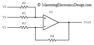
In a comment, one of my readers asked me what is the transfer function of the non-inverting summing amplifier in Figure 1, when R3 is connected to a reference voltage instead of ground.  Well, this is a summing amplifier with a differential configuration.

Figure 1

Read more

Differential Amplifier Output Common-Mode Voltage Calculator

A differential amplifier frequent use is the amplification of the voltage difference between its inputs, while rejecting the common-mode level.  However, the output common-mode level cannot be zero.  The operational amplifier technological limitations, as well as the outside resistor tolerances let the common-mode voltage to make it to the amplifier output as an output error.  As a consequence, the amplifier output voltage is the input signal difference times gain, plus the output common-mode voltage.

Read more

How to Design a Circuit from its Transfer Function Graph

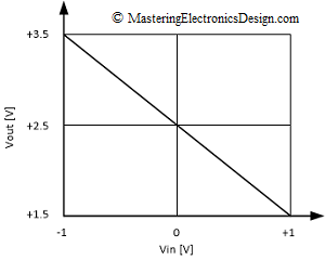
Sometimes all we know about a circuit is its transfer function graph.   The transfer function might look like the one in Figure 1.  How can we design a circuit so that its input-output behavior will match the graph?

Figure 1

The design starts with the mathematical form of the transfer function.  This is a linear function, with the general form of a first order polynomial function.

Read more

Differential Amplifier Calculator

Unipolar to Bipolar Converter Example

If you need to design a differential amplifier, here is a handy calculator. All you need to define are the input range, the output range and a choice of voltage reference.

The differential amplifier was explained in different articles on this website. Solving the Differential Amplifier – Part 1, Part 2 and Part 3 shows a numerical example and how to design such an amplifier. Also, the common mode voltage level and the common mode output error were explained in the series of articles The Differential Amplifier Common-Mode Error – Part 1 and Part 2.

Enter the input range, Vin1 to Vin2, the output range, Vout1 to Vout2 and a reference voltage Vref. You need to choose two resistors, R2 and R3. The calculator will compute R1 and R4.

Read more

Design a Differential Amplifier the Easy Way with Mathcad

For those of you who have Mathcad, designing a differential amplifier is really easy.

Let’s say you need to design a unipolar to bipolar converter and you decide to use a differential amplifier for this task. You know the input and output voltage range and you need to calculate the resistors based on a voltage reference you have in the system. All you have to do is to create a Mathcad file for a quick response. Then store it some place for future designs.

If you would like to know why the unipolar to bipolar converter can be designed with a differential amplifier, read this article, Design a Unipolar to Bipolar Converter for a Unipolar Voltage Output DAC .

Let’s take an example.

Read more

Design a Unipolar to Bipolar Converter for a Unipolar Voltage Output DAC

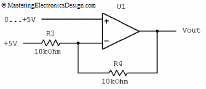
Unipolar to bipolar converters are useful when we have to have a unipolar component to do a certain job in a mixed signal design environment.  For example, Digital to Analog Converters (DACs) may have the output voltage range 0 to 2.5 V, or 0 to 5 V, while the design asks for a range of –5 V to +5 V.  To comply with this requirement, we have to design a unipolar to bipolar converter which will be inserted between the DAC output and the following bipolar stage.  It looks like the circuit in Figure 1.  How did I design it?

unipolar_to_bipolar_converter_1Figure 1

Read more

Show Buttons
Hide Buttons
'