For those of you who have Mathcad, designing a differential amplifier is really easy.
Let’s say you need to design a unipolar to bipolar converter and you decide to use a differential amplifier for this task. You know the input and output voltage range and you need to calculate the resistors based on a voltage reference you have in the system. All you have to do is to create a Mathcad file for a quick response. Then store it some place for future designs.
If you would like to know why the unipolar to bipolar converter can be designed with a differential amplifier, read this article, Design a Unipolar to Bipolar Converter for a Unipolar Voltage Output DAC .
Let’s take an example.
If you have a DAC that outputs 0 to +2.5V, with a reference of 2.5V, and you need a bipolar output of –1V to +1V, write down the differential amplifier transfer function as follows:
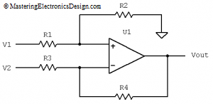
where the resistors are those in Figure 1. For the proof of this transfer function read How to Derive the Differential Amplifier Transfer Function.
Let’s rewrite the transfer function as a mathematical relation that depends on the resistor ratios R1/R2 and R4/R3.
This is the equation form we will use in Mathcad. I use it for clarity and to show the resistor ratios.
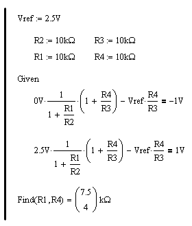
Open Mathcad and type the voltage reference and a choice for R2 and R3, say 10 kOhm. On the next line type some guess values for R1 and R4, say 10 kOhm also. These two resistors are the unknowns.
Next comes a solving block for two equations with two unknowns. The solving block is delimited by the keywords Given and Find.
Inside the solving block lets write the differential amplifier transfer function in two instances, one when the output voltage is –1V and one for +1V. I also replaced V2 with Vref and V1 with the input signal. The Mathcad code should look like this:
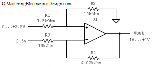
 The “Find” function gives the answer in the form of a matrix of one column and two rows. For this example, R1 = 7.5 kOhm and R4 = 4 kOhm. Choose the standard values of 7.5 kOhm 1% and 4.02 kOhm 1% respectively. During the Mathcad calculations I prefer to attach the units as well. If there is a mistake, Mathcad will flag that the units do not match. This is a great way to verify your equations and assumptions on fly.
Figure 2 shows the final schematic.


I applied this method and it works great. For some input/output ranges I am getting a negative value for R1 or R4. Why is that?
A negative resistance is theoretical. The system of equations has a solution, but the solution is negative. It means that your design needs an extra source of energy in order to output the voltage range you need for the given input range. In practice, you have two choices: change the reference voltage, or change the amplifier topology. A lot of times it is easier to change the reference value than to change the op amp configuration. This method is great because it lets you find the correct resistor values by trying different voltage references.
Which Mathcad version did you use?
I used Mathcad 2001. However, any version between 2001 and Mathcad 14 would work the same.
where can i get Mathcad.Is there a Mathcad equivalent that works on Linux.
Mathcad is owned and distributed by PTC. Here is the link:
http://www.ptc.com/products/mathcad/
They have a trial version and also a student version. I am not aware of any Linux version.
Great article. Precise and brief. Great job
A free and cross-platform (i.e. it works on Linux) Mathcad-like alternative is:
http://en.smath.info/
which also has a cloud version.
It is not as extensive as Mathcad but it is very like Mathcad to use and should handle the Mathcad calculations given here.
Thank you, Andy, for you comment. I was not aware of this math program. I will check it in the next few days.
Hi ,
In my difference amplifier configuration the DAC ouput(120mv to 3.4v) is feed
to inverting terminal of opamp and 2.5Vref is applied to non-inverting terminal. The opamp output should be +10V for 120mv input along with 2.5vref and -10V for 3.4 input along with 2.5 Vref.
can i use same transfer function. please advice me.
Thanks
Ayyappan
Use the calculator I have here:
Differential Amplifier Calculator (https://masteringelectronicsdesign.com/differential-amplifier-calculator-2/)