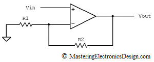
One of the most common amplifiers in Analog Design is the non-inverting amplifier.
Figure 1
Its transfer function is
| (1) |
How do you derive this function?
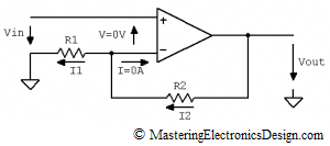
Let’s first note that we can consider this Op Amp as ideal. As such, the current in the inverting input is zero (I = 0A, see Figure 2) and the currents through R1 and R2 are equal.
| (2) |
Figure 2
Next, we can write an equation for the loop made by Vout, R2, V and Vin.
| (3) |
From equation (3) the I2 expression is
| (4) |
In a similar way we can determine the expression for I1. Equation (5) is the loop equation for R1, V1 and Vin.
| (5) |
and
| (6) |
Being an ideal Op Amp, we can consider that the non-inverting input is at the same potential as the inverting input, so V = 0V. This is due to the high gain of the ideal Op Amp. When the output is at a level of a few volts, the differential input can be at a level of some tens of microvolts. Hence, V is very close to zero.
Replacing I1 and I2 in equation (2) and eliminating V, we can write this equation:
| (7) |
Therefore, the transfer function of the non-inverting amplifier is
| (8) |
Q. E. D.


what is the solution if R1=0 and Vin is applied with a series resistance ?
I am curious. Why would you make R1 zero? What would be the physical accomplishment?
if in the example circuit you make r=zero, the op amp will behave like a buffer.
i mean r1=0.
No. To become a buffer you need to remove r1.