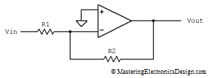
In my articles I talked about the op amp virtual ground and sometimes I wrote a brief explanation of this concept. In this article I will show you why an op amp input can be considered at a zero potential, without being galvanically connected to ground. Let’s take a simple circuit, the inverting amplifier.
In MasteringElectronicsDesign.com : How to Derive the Inverting Amplifier Transfer Function I showed the proof of its formula by using the virtual ground. The inverting input is at a zero potential, therefore virtual ground, which is a direct consequence of the feedback provided by R2 and the op amp high gain. Let’s see why.
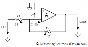
This time let’s consider that the op amp does not have an infinite gain. Let’s consider it finite and note it with A, as in Figure 2. Let’s note the inverting input potential with V. We need to show that V has a low voltage level, so let’s calculate it.
The feedback current I2 can be written as
| (1) |
Also, I1 can be written as
 |
(2) |
An op amp has small input currents, which are usually neglected in calculations. As such, I is zero, so we can write I2 = -I1 as in the following equation.
| (3) |
This equation can also be written as
| (4) |
where I noted k = R2/R1 to simplify the calculations.
The circuit output voltage dependence on the op amp gain and the difference between the inverting and non-inverting input is
| (5) |
Eliminating Vout from equations 4 and 5 we have
| (6) |
and V results as
| (7) |
An op amp has a large gain. For example, Linear Technology’s LT1028 has a typical gain of 30 V/uV. This means a gain of 30,000,000. Since the op amp gain appears in equation 7 denominator, V is extremely small and can be considered zero. Hence, the virtual ground. That is why we can consider that the inverting input, in the inverting amplifier shown in Figure 1, is at zero potential. At the same time, the same type of reasoning can lead us to considering that both inputs of the operational amplifier are at the same voltage level. This is valid providing that the amplifier operates correctly, with no saturated outputs. Such approximation is usual in electronics industry and greatly simplifies calculations. I used it in proofing the transfer function of different amplifier configurations in this website.
== == ==
The Transfer Function of the Inverting Amplifier with a Finite Op Amp Gain
Using the same equations we can study the influence a finite op amp gain has on the inverting amplifier transfer function.
If, in equations 4 and 5 we eliminate V, the result is the inverting amplifier transfer function.
| (8) |
and
 |
(9) |
so the transfer function is
 |
(10) |
The transfer function (10) shows that, if A is high as with the majority of operational amplifiers, the fraction (1+k)/A is negligible, so the transfer function of the inverting amplifier becomes the well known
| (11) |
as shown in MasteringElectronicsDesign.com : How to Derive the Inverting Amplifier Transfer Function.
In literature you may find the inverting amplifier transfer function (10) in the following form:
 |
(12) |
which shows the circuit open loop gain, (A+1) (1/k). But, we will discuss the open-loop gain in a future article.


Thank you!!! This helped me a lot