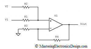
The summing amplifier, or the non-inverting summing amplifier, is an analog processing circuit with the transfer function (the summing amplifier formula as some say) shown in the following equation.
| (1) |
The first term of the product is the actual summing, while the second term is a gain due to the R3 and R4 resistors. I prefer this type of summing amplifier as shown in Figure 1, because it is more flexible and allows us to achieve any linear function we want.
Figure 1
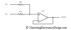
Some authors prefer the following schematic,
Figure 2
with the transfer function
| (2) |
One can see that the summing amplifier in Figure 2 is a subset of my preferred schematic in Figure 1. In Figure 2, R4 is zero, while R3 is infinity (open connection). It performs the analog summation between V1 and V2, with a gain of 1. Therefore, the amplifier in Figure 1 gives us more choices when designing a function with this circuit. If the gain is not needed, this should come up from calculations, as in this article Solving the Summing Amplifier.
If you followed this website, by now you probably figured that I am not a promoter of learning formulas by heart. I like to derive the transfer function if I need it. So, how do we prove this formula?
We will use the Superposition Theorem, which says that, the effect of all the sources in a circuit is equal with the sum of the effects of each source taken separately in the same circuit. Therefore, if we take out one source, V2, and replace it with a wire, we then can find the voltage in each node and the current in each branch of this circuit due to the remaining source V1. Then we do the same with V1 and then sum up the currents on each branch and the voltage levels on each node. We are only interested in Vout, so this should be simple.
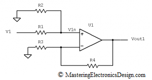
We will first make V2 = 0V, by connecting R2 to ground, as in Figure 3.
Figure 3
The Op Amp is considered an ideal component, so that the input bias currents are negligible. If the current in the non-inverting input is zero, R1 and R2 make a voltage divider for V1. The non-inverting input voltage V1n, can be written as
| (3) |
and, based on the non-inverting amplifier transfer function, Vout1 is
| (4) |
By replacing V1n in (4), the output voltage is
| (5) |
In the second part of my demonstration, based on the Superposition Theorem, R2 is connected back to V2 and V1 = 0, by connecting R1 to ground. Following the same train of thought Vout2 can be written as
| (6) |
Now we have to add Vout1 to Vout2 to complete the third step of the Superposition Theorem. After factorizing the gain component 1+R4/R3, the summing amplifier transfer function becomes the mathematical relation shown in (7).
| (7) |
Q.E.D.
>>> <<<
This formula shows that this sum is a weighted sum between V1 and V2. This is better than a direct sum V1 plus V2, because, again, brings flexibility in design. Together with the differential amplifier, this circuit brings another treat in the art of electronics design.


how do you proof the transfer function of the summing amplifier with 4 inputs? i saw this some place, i forgot where, but no proof.
It should be the same with the superposition theorem but it gets more complicated.
Yes, it is more complicated but not unbearable. Najit’s question just gave me an idea. I will write an article where I will demonstrate the transfer function of a summing amplifier with multiple sources, up to “n” sources. This should be interesting. It should also answer Najit’s question.
===================================
Update: I wrote this article. Please go to The Transfer Function of the Summing Amplifier with “N” Input Signals.
Thanks for this interesting article.
I have been searching on how to proof the summing amplifier with the superposition theorem. Your article helped a lot. Looking forward for the summing amplifier with n inputs.
Thank you.
Just wanted to say HI. I found your blog a few days ago on Technorati and have been reading it over the past few days.
Hi, great post. I have been searching for the non-inverting summing amplifier transfer function,so thanks for posting.
I bookmarked this link. Thank you for good job!
wow i love this
I recently came across your blog and have been reading along. I thought I would leave my first comment. Nice blog. I will keep visiting it often.
Very nice! Thank you so much!
You may want to check this discussion before you use this in a circuit:
http://forum.allaboutcircuits.com/showthread.php?p=170314
The input resistance to your summer will change based on the input voltages. This could be ok if you prevision for it in your design, but the non-inverting summer is not as “plug and play” as it is made out to be here.
Great article otherwise.
Gould, thank you for your input. You bring a good point here. For those readers that do not have time or patience to follow that thread, here is a short summary: the forum thread concludes that the inverting summing amplifier is preferred versus the non-inverting one due to the fact that the input currents vary as the input signals change. Indeed, if we look at Figure 1, the input current through R1 is Iin1 = (V1-V2)/(R1+R2). When the input current fluctuates independently of its own source, it creates a perceived input impedance variation that appears uncontrollable.
While this is true, one has to take it with a grain of salt, like with any other circuit. I always use an Op Amp in each input, to minimize the input source impedance. If that source Op Amp has a negative feedback, its output resistance is even more reduced (see this article, The Non-Inverting Amplifier Output Resistance). Also, non-inverting summing amplifiers are widely used in bipolar to unipolar converters (see this article, Design a Bipolar to Unipolar Converter to Drive an ADC). In that case, the second input voltage does not change in time, so that the input impedance does not change independently of the main input source. Non-inverting summing amplifiers are also used to implement arbitrary linear functions, as described in Solving the Summing Amplifier).
As with any other electronic circuit, one has to think about the requirements of his/her project before using this circuit. I design high-end instrumentation equipment and many times I prefer the non-inverting summing amplifier versus the inverting one, because the inverting amplifier needs another amplifier at its output to invert the signal again. This adds cost, extra noise and offset in the signal chain which I prefer not to have. Moreover, when I design low voltage circuits, sometimes I do not have a negative supply, so going negative is not an option. I have to stay in the positive realm and the non-inverting summing amplifier does a good job for me.
In any case, indeed, one has to use this circuit with care.
Mr. Nastase, this is a great site full of practical and useful information. Thank you for putting this up! I do have a question that I am sure you can answer. How does the transfer function of Figure 1 change if R3 is tied to a reference voltage instead of zero potential? Thank you!
Thank you David. I really appreciate that.
As for your question, if you connect R3 to a reference voltage, say V3, the circuit output is shifted by –V3*R4/R3. The new transfer function is:
Vout = ((V1*R2/(R1+R2) + V2*R1/(R1+R2)) * (1+R4/R3) – V3*R4/R3
Hope this helps for now. I will write a short article to prove this. If you wish, please use the RSS or Facebook subscription to be notified.
===============
Update: I published this article. You can find it here:
A Summing and Differential Amplifier with One Op Amp
Very helpful source and it help me a lot especially when some of my lecture notes did not really help me a lot in understanding fully of some particular topic related. Thank you very much for the blog. Credit for you.
Thanks.
Thanks Aries. Glad you find this website useful.
How I can write PM to other users? Thanx
I believe you ask about sending personal messages to the other users of this website. For this you need a forum. I do not have a forum yet. I plan to have one in the future. If any of you would like to be forum administrator(s) please let me know. In the mean time you can post responses to other people’s comments.
I am glad I fond this site!. Very easy to understand. All of the books only show inverting summing amplifiers but I need to design a non-inverting one. I thought it was complicated before. But when I saw your transfer function, I immediately realized that you used the Superposition Theorem to get the solution. Thanks a lot!
Thank you for your comment Godwin. I am glad that this website helped you.
Thank you! As an ME student having to take a circuits class, this has made things make much more sense.