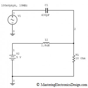
In allaboutcircuits.com forum, a question was posted: How can I combine an AC source of known frequency and amplitude with a DC power supply?
I thought this is an interesting problem, so here is the solution.
Subsequent messages clarified the requirements: 5V power supply, and the load needs 0.5A, which would make the load 10 ohms. The signal that rides on top of the DC voltage has to be 20 mVpkpk.
First, we need an inductor in series with the power supply to block the AC component. In this schematic, V1 is the 10 MHz generator and V2 is the 5V power supply.
The inductor’s impedance should be at least 10 times higher than the load, so that most of the generator energy goes into the load. If we note XL the inductor impedance, then XL = 10·RL, so XL = 100 ohms, and L1 can be calculated
The result is L1 = 1.59 uH, with a standard value of 1.8 uH.
Then, we need a capacitor in series with the generator, to block the DC component from coming into the generator output. The generator, through this capacitor, “sees” the load in parallel with the inductor, considering that the power supply output impedance is low, close to zero. Because of that, the capacitor impedance, together with the parallel combination load and inductor impedance form an attenuator. The signal amplitude on the load, can be written as follows:
where VL is the AC signal amplitude on load, VG is the generator amplitude, RLparXL is the load and inductor in parallel
and XC is the capacitor impedance. Using the above relation the capacitor impedance becomes
Taking into consideration that VL = 20 mVpkpk, L = 1.8 uH and choosing the generator amplitude VG = 100 mVpkpk, C1 becomes
with the result C1 = 433.07 pF. A standard value for C1 is 430 pF.
The generator amplitude can be slightly adjusted around 100 mVpkpk, so that the signal on load is exactly 20 mVpkpk.
And what is the current the generator sources on load? This can be easily calculated noting that the generator “sees” a capacitor in series with RL in parallel with L1. Since XC + RLparXL = 45.94 ohms, the generator output current is 2.18 mApkpk.
A 0.5 A, 1.8 uH inductor can be easily found. The generator sends into the power supply approximately 0.2 mApkpk signal. If this is not desirable, the inductor value can be increased with the disadvantage that its size increases.
Note that this method considers the load as being pure resistive. If the load has reactive components, RL has to be replaced by the combined impedance values of the resistive and reactive components.


I am trying to work the formula for L1 and the numbers just don’t add up. My circuit in somewhat different, in that my frequency is 15kHz and my load is 10mA, but the final desired outcome is the same. When I try to calculate the values for L1 (for example) as stated, I don’t come up with 1.58, my calculation is 3.1830 (I assume this is Henry’s). Is there an error on the website or a misunderstanding on my part? What am I doing wrong?
What is the load in ohms? If the voltage is 5V, with 10 mA load current, then your load is 500 ohms. You want your inductor impedance to be 10 times higher, at 5 kohm. Therefore, L1 = 5 kohm / (2 * PI * 15 kHz) = 53 mH.
I need to add a 1Vp-p, 50 Hz sine wave on 12VDC so I determined that I needed a 1.0H inductor (very big and heavy) and some value of capacitor (I forget exactly). Anyways, I built it with a 48 ohm power resistor (actual load needs 250mA) and it worked very well. I ended up having to increase the DC voltage a little to over come the internal DC resistance of my inductor to get my required 12VDC at my load, but it worked until I plugged in my actual load. The DC output oscillates like a square wave around 5 Hz! I am not sure why this is happening. The load has about 20uF capacitance and internal DC-DC regulators and switchers. The best answer I can think of is that maybe the internal DC-DC switcher/regulators shut down perhaps due to an over voltage condition??? Or maybe the DC input rise time is too slow and causes some weird condition inside??? I have now removed the AC and capacitor and just have my benchtop DC voltage generator to this large inductor to my load. Any thoughts of what could be happening?
I would guess that your inductor together with the capacitive load create a tank with a self resonant frequency of 5 Hz. Or, it may be that your 12 V power supply is overloaded and goes into protection mode (it folds) oscillating between on and off. Good supplies should stay folded until you power cycle them.
Can you inject an AC pulse without the inductors?
No. Without the inductor the power supply will short-circuit the AC signal generator.
Thank you very much. It is a great article. Could you recommend a book which describes this method?
I would like to superimpose a sine wave on top of a square wave.
Simply add the two signals.