Build an Op Amp SPICE Model from Its Datasheet – Part 3

MasteringElectronicsDesign.com:Build an Op Amp SPICE Model from Its Datasheet – Part 1 and Part 2 show you how to build an Op Amp SPICE model based on the manufacturer’s datasheet. We talked about modeling the offset voltage, the input resistance and capacitance both common-mode and differential, the output resistance and the frequency domain behavior.

In Part 2, we left off at the open-loop bode plot. We saw that it resembles the datasheet. However, our op amp example, ADA4004 from Analog Devices, shows an extra pole after 1 MHz. Indeed, the phase starts dropping after 1 MHz and becomes 45 degrees at 17 MHz. Therefore, we need another pole in our model at 17 MHz.

Introducing the Second Pole

The pole can be introduced using the same technique we used in Part 2. We will use an RC Norton source. Since the DC open-loop gain is already set by the first pole, we only need to make sure that the choice of current and resistor does not affect the DC gain. This second pole influence has to be only at high frequencies. At low frequencies its gain should be 1, so that the overall open-loop gain remains 500000.

Read more

Build an Op Amp SPICE Model from Its Datasheet – Part 2

Part 1 of this article (http://MasteringElectronicsDesign.com/buildi-an-op-amp-spice-model-from-its-datasheet/) shows how to create a behavioral model of an operational amplifier based on the following parameters found in the datasheet: Input and output resistance, input capacitance, DC gain, and offset voltage. As an example I chose Analog Devices’ ADA4004. Let’s continue building this model to simulate the Gain Bandwidth Product.

Gain Bandwidth Product

The Gain Bandwidth Product, describes the op amp behavior with frequency. Op amps have a dominant pole, inserted by manufacturers on purpose, so that the op amp is stable at any gain down to zero dB. See this article for more details: MasteringElectronicsDesign.com:An Op Amp Gain Bandwidth Product. In that article I showed that ADA4004 has a cutoff frequency at 24 Hz. This frequency is not identified in the datasheet, but can be easily calculated from the open-loop minimum gain of 500000 and the gain bandwidth product of 12 MHz.

Starting with the cut-off frequency, the open loop gain versus frequency plot has a drop of 20dB for every decade of frequency. To simulate this we need to introduce this pole in our SPICE model. Question is, how?

Read more

Why do I do this?

Since MasteringElectronicsDesign.com was born my friends asked me, why do I do this? Why do I spend my time writing at this blog? The answer is simple, I enjoy it.

Over time, I realized that I like answering questions regarding different subjects in electronics design. And people sense this. No matter what company I worked for, somehow my colleagues realized that they can ask questions and that I always would answer them. So I got this idea to start a blog about electronics. I was amazed of how many people visited its pages in the first month. The response was huge for a just born website.

When I started this blog I looked for an open source CMS (Content Management System) and I realized that the best that would suit my needs was WordPress. Its simple platform allowed me to start from zero articles and then grow it in time. I created my own WordPress theme by adapting the default one. I also like to use PHP, so this was a bonus.

Read more

An Op Amp Gain Bandwidth Product

I can see some chat on internet about the operational amplifier gain bandwidth product. People are interested in having a better understanding of this parameter, as it appears in any op amp datasheet and it is used in many articles and books. In this article I will describe this parameter and show you an example with Analog Devices’ ADA4004, which is a precision amplifier.

The Gain Bandwidth Product describes the op amp gain behavior with frequency. Manufacturers insert a dominant pole in the op amp frequency response, so that the output voltage versus frequency is predictable. Why do they do that? Because the operational amplifier, which is grown on a silicon die, has many active components, each one with its own cutoff frequency and frequency response. Because of that, the operational amplifier frequency response would be random, with poles and zeros which would differ from op amp to op amp even in the same family. As a consequence, manufacturers thought of introducing a dominant pole in the schematic, so that the op amp response becomes more predictable. It is a way of “standardizing” the op amp frequency response. At the same time, it makes the op amp more user friendly, because its stability in a schematic becomes more predictable.

Read more

Build an Op Amp SPICE Model from Its Datasheet – Part 1

Why do you need to build your own Op Amp model? Most Op Amp manufacturers have SPICE models for their components and make them available for free. Then why should you know how to build one? Well, not everything has a model and that is why, sometimes, you have to build your own. Also, it may be necessary to study a circuit to see what happens if you change the Op Amp slew rate or bandwidth, offset, and so on. Sometimes the manufacturer own model does not work, as a user found out and posted a question in this forum. I told him that the model has a bug and advised him to build his own.

No matter the reason, building your own model is fun and rewarding and can only add to your overall understanding on how an Op Amp works. One note of caution. The model described here is a behavioral model. This means that the model will mimic the op amp functionality, but will not have any transistor or any other semiconductor SPICE models.

Read more

An Ideal Operational Amplifier Simulation Model

You worked hard on your schematic, you calculated everything, you feel confident that it will work.  To be sure though, before committing the schematic to copper, you want to simulate it.  You develop a SPICE simulation schematic and, surprise, things don’t work.  What’s going on?

You start searching for bad connections in the simulation schematic.  You check the power supplies and the circuit biasing.  Finally, in desperation, you suspect the operational amplifier model that you downloaded from the manufacturer website, or found in the SPICE program library.  How do you troubleshoot your circuit?

First, split your circuit into small subcircuits, like a one op amp circuit.  Second, take aside, on a different simulation page, one of these subcircuits.  Is that working?  If that circuit is a non-inverting amplifier, as an example (Figure 1), and the output voltage is all over the place except your expected value, than replace your op amp with an ideal one and see if that circuit works.

Read more

The RMS Value of a Trapezoidal Waveform – Part 2

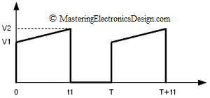
In a previous article, MasteringElectronicsDesign.com:How to Derive the RMS Value of A Trapezoidal Waveform – Part 1, I showed how to derive the RMS value of a trapezoidal signal with a flat plateau and different rise/fall time values.  In some applications, the trapezoidal signal plateau is not flat, but rather a ramp, as shown in Figure 1.  A typical example is a DC-DC converter, where the transformer winding current might look like the signal in Figure 1.  Of course, in the DC-DC converter example, the amplitude is current and not voltage.  No matter, the calculations are the same.

This waveform is still considered a trapezoidal waveform. Let’s calculate its RMS value.

trapezoidal-waveform-2Figure 1

Read more

Show Buttons
Hide Buttons
'