Using the Summing Amplifier as an Average Amplifier

Sometimes people ask how can one use a summing amplifier as an average amplifier. The answer is simple, provided that one knows what kind of average one needs.

The summing amplifier can output the average of two, three or more signals. This is different than a signal average. The summing amplifier cannot, for example, output the average of a triangle signal. For that, you need an integrator to perform the average in the analog realm, or you need to sample the signal and calculate the average with a microcontroller. This type of average is the signal average in the time domain. I will write an article about the average of a signal in a near future.

In this post I will show you how to average two or more signals with a summing amplifier. In How to Derive the Summing Amplifier Transfer Function I wrote that the summing amplifier shown in Figure 1

Read more

Playing Engineer in Kindergarten

Yesterday New York Times published an article with the title Studying Engineering Before They Can Spell It. The article talks about students at an elementary school in Glen Rock, NJ, who have engineering study in their curriculum. These students cannot even spell the word engineer correctly, but they learn and experiment how to solve engineering problems. While the supporters say that “engineering reinforces math and science skills, promotes critical thinking and creativity”, some question if the children are really learning something and if the school should spend on this program.

Really? Why would someone question this program?  It is the age when the engineering bug catches and it will hold the child, and then the young adult, and then the engineer for years to come. It is the age when the love for one’s profession develops.

I am not talking in clichés. I know this first hand. I was fortunate enough to have Uncle Manea in my life who had a small business, a shop where he would repair anything electrical, from steam irons to TV sets. I was nine years old when I first went to his shop. I was fascinated. I started to help him by rewinding burned transformer bobbins and, later on, doing small electrical repairs. I just loved it, and that love for electronics lasted a life time.

Read more

How to Derive the RMS Value of Pulse and Square Waveforms

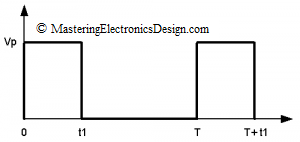
The RMS value of a pulse waveform can be easily calculated starting with the RMS definition. The pulse waveform is shown in Figure 1. The ratio t1/T is the pulse signal duty-cycle. As shown in other articles in this website (MasteringElectronicsDesign.com:How to Derive the RMS Value of a Trapezoidal Waveform and MasteringElectronicsDesign.com:How to Derive the RMS Value of a Triangle Waveform), the RMS definition is an integral over the signal period as in equation (1).

pulse signalFigure 1

Read more

How to Derive the RMS Value of a Triangle Waveform

What is the RMS value of a periodic signal?  When a periodic signal is generated by a source connected to a load, a resistor for example, the RMS value is the continuous signal, the DC value which would deliver the same power to the load as the periodic signal.

This article shows how to derive the RMS value of triangle waveforms with different shapes and duty cycles.

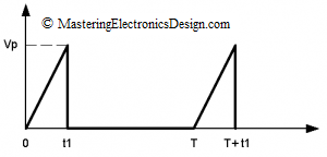
The triangle waveform in Figure 1 has a slower rise time than the fall time.  In this case, the fall time is small so that it can be considered zero.  If it is not zero, read further on deriving the RMS value of a triangle with comparable rise and fall times.

triangle waveform with slow rise time, sharp fall timeFigure 1

Read more

How to Derive the RMS Value of a Trapezoidal Waveform – Part 1

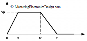
In this article I will show you how to calculate the RMS value of a trapezoidal waveform. This periodic waveform is shown in Figure 1. It has a rise time from 0 to t1 and a fall time from t2 to t3. The plateau is between t1 and t2, and the signal is periodic with the period T. If you know this, then you can derive the RMS value of a triangle, square and pulse waveform as well.  Go to How to Derive the RMS Value of a Triangle Waveform and How to Derive the RMS Value of Pulse and Square Waveforms for further reading.

Figure 1

Read more

A Summing and Differential Amplifier with One Op Amp

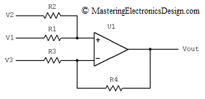
In a comment, one of my readers asked me what is the transfer function of the non-inverting summing amplifier in Figure 1, when R3 is connected to a reference voltage instead of ground.  Well, this is a summing amplifier with a differential configuration.

Figure 1

Read more

An ADC and DAC Least Significant Bit (LSB)

Articles on Internet and books show how to calculate the Least Significant Bit (LSB), but they take into consideration either the voltage reference (Vref) or the full scale (FS) of the ADC or DAC.  Many times this leads to confusion, as a few messages I received from my readers show.  Therefore, this article shows both ways of defining the LSB, so that people will have a clear understanding how to treat an ADC’s (Analog-to-Digital-Converter) or DAC’s (Digital-to-Analog-Converter) LSB.

Read more

Show Buttons
Hide Buttons
'