Sometimes people ask how can one use a summing amplifier as an average amplifier. The answer is simple, provided that one knows what kind of average one needs.
The summing amplifier can output the average of two, three or more signals. This is different than a signal average. The summing amplifier cannot, for example, output the average of a triangle signal. For that, you need an integrator to perform the average in the analog realm, or you need to sample the signal and calculate the average with a microcontroller. This type of average is the signal average in the time domain. I will write an article about the average of a signal in a near future.
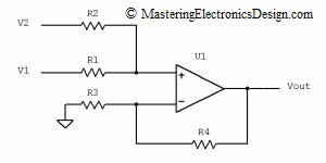
In this post I will show you how to average two or more signals with a summing amplifier. In How to Derive the Summing Amplifier Transfer Function I wrote that the summing amplifier shown in Figure 1
has the following transfer function:
| (1) |
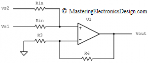
If R1 and R2 are equal, and equal with a common value Rin, as in Figure 2,
Figure 2
the new transfer function becomes
| (2) |
The equation shows that, when R1 = R2 the amplifier output level is the average between the two input signals times the gain of 1 + R4/R3. In reality, the two resistors cannot be perfectly equal, due to tolerances, so you will still have to use equation (1) for a correct calculation of the output signal. Still, if you choose matched resistors, the output will be very close to the theoretical expression of equation (2).
Now, the fact that Rin does not count in the average transfer function does not mean that Rin can be any value. This resistor has to be chosen carefully, because it dictates the loading of the input signals. Indeed, looking at the amplifier in fig 2, if we write the loop equation for V1, Rin, Rin, V2, and consider that the current in the op amp input is insignificant, the loop current is
| (3) |
Therefore, the smaller Rin is, the larger the current sourced/sunk by V1 and V2. If we choose Rin in the kiloohms or tens of kiloohms range, the loading on the input signals will not be significant for the usual op amp voltage levels.
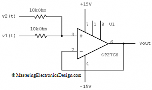
As an example, the summing amplifier in Figure 3 is an average amplifier with two input signals, made with Analog Devices’ OP27GS.
Figure 3
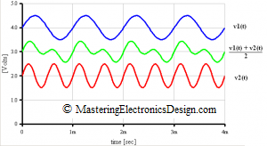
The first signal, v1(t) has a frequency of 1 kHz, an amplitude of 0.5V and rides on a 4V DC level. The second signal, v2(t) has a frequency of 2 kHz, an amplitude of 0.5V and rides on a 2V DC level. Every moment in time the amplifier performs the average between the two signals. The waveforms are shown in Figure 4, where the output signal is shown with green. For this example I removed the gain resistors R4 and R3 to better illustrate the average of the two input signals. In this case, the average amplifier has a gain of one, so that the output signal lands exactly between input signals as in Figure 4.
Figure 4
But what if we have 3, 4 or more input signals and we need to build a circuit that outputs the average of all these signals?
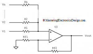
In The Transfer Function of the Non-Inverting Summing Amplifier with “N” Input Signals I demonstrated the transfer function of a summing amplifier with multiple inputs (see Figure 5).
Figure 5
In that article I showed that the transfer function is
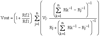 |
(4) |
where j counts the input signals and k the input resistors.
The average of n input signals can be achieved the same way as we did with the summing amplifier in Figure 1. We will make all input resistors equal, so that R1 = R2 = … = Rn = Rin, then we can reduce the parenthesis to a simple expression as in equation (5),
 |
(5) |
where with Rin I noted the common value of the input resistors.
In this case Vout becomes
 |
(6) |
and, reduced even more,
 |
(7) |
Equation (7) is the output level of an average amplifier with n input signals and with the gain of 1 + Rf2/Rf1. One can easily see that equation (7) is the same as equation (2) when n = 2.
>>> <<<


