What is INL? This term describes the non-linearity of Analog to Digital Converters (ADC) and Digital to Analog Converters (DAC). INL stands for Integral Non-Linearity. Is this term important? Should we be concerned about this specification? The answer is yes.
INL is considered an important parameter because it is a measure of an ADC or DAC non-linearity error. However, as in any Analog or Mixed-Signal Design project, some specifications are important, some are not. It all depends on the project requirements regarding accuracy and precision. Understanding INL enables the circuit designer to avoid surprises in his or her project.
The Integral Non-Linearity is defined as the maximum deviation of the ADC transfer function from the best-fit line. An ADC function is to digitize a signal into a stream of digital words called samples. The ADC output is discrete as opposed to the input, which is continuous. It is used at the boundary between the analog and digital realms.
The ADC input is usually connected to an operational amplifier, maybe a summing or a differential amplifier which are linear circuits and process an analog signal. As the ADC is included in the signal chain, we would like the same linearity to be maintained at the ADC level as well. However, inherent technological limitations make the ADC non-linear to some extent and this is where the INL comes into play.
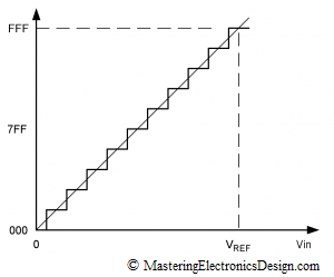
Figure 1
Figure 1 shows the ADC transfer function. For each voltage in the ADC input there is a corresponding word at the ADC output. The figure shows a 12-bit ADC where the steps were exaggerated for better viewing. The y axis, the output, is digital, so that the values are represented in hexadecimal format. If the ADC is ideal, the steps shown are perfectly superimposed on a line.
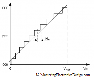
Figure 2
Figure 2 shows an ADC with a slight non-linearity. To express the non-linearity in a standard way, manufacturers draw a line through the ADC transfer function, called the best fit line. The maximum deviation from this line is called INL, which can be expressed in percentage of the full scale or in LSBs (List Significant Bit). INL is measured from the center of each step to that point on the line, where the center of the step would be if the ADC was ideal.
This parameter is important because it cannot be calibrated out. The ADC non-linearity is unpredictable. We don’t know where on the ADC scale the maximum deviation from the ideal line is. Therefore, if one of the design requirements is good accuracy, we need to choose an ADC with the INL within the accuracy specifications, or a lot less than the specified error.
For example, let’s say the electronic device we design has an ADC that needs to measure the input signal with a precision of 0.5% of full-scale. Due to the ADC quantization, if we choose a 12-bit ADC, the initial measurement error is +/- 1/2 LSB which is called the quantization error.
With the ADC quantization error almost 40 times lower than the design requirements, a 12-bit ADC can do a good job for us. However, if the INL is large, the actual ADC error may come close to the design requirements of 0.5%. We would like to keep each component error in the circuit as low as possible, so that the total combined error of the electronic device we design is less than 0.5%. Gain or offset errors in an ADC can be calibrated out, but INL cannot. If we need to live with an evil, at least we need to choose an ADC with a small INL. This may increase the cost we allocate for the ADC in the system, but it is worthwhile if we are to keep our promises and design a device within specifications.
The DAC Integral Non-Linearity can be viewed the same as for an ADC. The only difference is that, with a DAC, the INL may not be as important. If the DAC is used to set a few voltage levels in a system, those values may be easily calibrated, so we can choose a low cost DAC. However, if the DAC is used to accurately restore a dynamic signal, the INL cannot be easily calibrated. In that case, we need to choose a high precision DAC, with a good INL.


You briefly wrote about the dac calibration. How do you calibrate a DAC?
Hi,
A broad maybe unanswerable wrong question from me but in hopes to find the solution or path.
Example:
I’m calibrating a 1.5kw 50ohm 208v generator and the DAC count is too low.
It is a cal/verify test.
My points are 6/10/15
I know its hard without seeing actual stuff,
I am looking to calibrate the counts in a front panel window, to the pots on a measurement board.
Is there a specific adjustment typically on the measurement board that boost the DAC count ?
Or would my analog, digital board or 186 or MB have something also?
Op amp? / gain?
I made gain adjustments on a 5.5kw 50ohm 400v and it worked fine.
But the problem is that changing the fwd gain, it had to be changed each time during test, but in command line passed like a charm.
Any idea why the EEPROM had to be kept re adjusting?
Hope I’m clear enough…
I need to see a schematic or a block diagram at the very least. For the moment, if I understand this correctly, I can tell you that if adjusting the DAC you only have 6/10/15 counts, that is too low. It means that the DAC maximum voltage is too high.
The solution is to create an attenuator after the DAC, that will bring the DAC full range to the maximum voltage you need for calibration. That way, instead of 15 counts maximum, you will have the full DAC counts, 256 for and 8-bit DAC or 4096 for a 12-bit DAC.
If you are interested to continue this discussion answer here, and I will send you my email address.
A DAC, like any other active component, has an offset and a gain error. With calibration, one will determine what digital values should the DAC receive to output the exact absolute voltage level the system needs. If the DAC is linear, a two point calibration would suffice to determine the exact linear transfer function. Once you know the transfer function, the system is calibrated.
If the DAC is non-linear, in other words, the INL is high, a two point calibration is not enough. Depending on the DAC transfer function non-linearity, the calibration can be achieved with a few points and then interpolation, or with a look up table and interpolation.
More about this in a future article.
This is a very understandable and compact description. Thank you very much!
specification parameters that must be considered when choosing an ADC and a DAC other than INL?
You need to consider the ADC or DAC resolution (or the number of bits), the reference voltage, what kind of digital interface (parallel, SPI, I2C), the signal-to-noise ratio. It really depends on your application. Any ADC/DAC datasheet will show you these parameters.