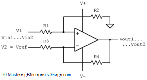
Unipolar to Bipolar Converter Example
If you need to design a differential amplifier, here is a handy calculator. All you need to define are the input range, the output range and a choice of voltage reference.
The differential amplifier was explained in different articles on this website. Solving the Differential Amplifier – Part 1, Part 2 and Part 3 shows a numerical example and how to design such an amplifier. Also, the common mode voltage level and the common mode output error were explained in the series of articles The Differential Amplifier Common-Mode Error – Part 1 and Part 2.
Enter the input range, Vin1 to Vin2, the output range, Vout1 to Vout2 and a reference voltage Vref. You need to choose two resistors, R2 and R3. The calculator will compute R1 and R4.
Given Input Range
| Vin1 = | V | Vin2 = | V |
Required Output Range
| Vout1 = | V | Vout2 = | V |
Choose a Reference Voltage
| V2 = | V |
Choose R2 and R3
| R2 = | kOhm | R3 = | kOhm |
Calculate R1 and R4
| R1 = | kOhm | R4 = | kOhm |
The default values for this calculator are set for a unipolar to bipolar converter. An explanation of this circuit and another example can be found in Design a Unipolar to Bipolar Converter for a Unipolar Voltage Output DAC. This calculator solves a system of 2 equations with 2 unknows, R1 and R4. Such a system will always have a solution, but the solution might not be physically possible. For example, if one of the resistors is negative, you will need to change the input data. Usually, changing the reference voltage will bring the resistors in the positive realm.


Your calculations are in contradiction with
https://www.daycounter.com/Calculators/Op-Amp/Op-Amp-Voltage-Calculator.phtml
What is the contradiction? I do not see any.
Hi in my design I am supplying2.5 vref to noninverting terminal. And input to the inverting terminal ranges from 120mv to 3.4.v. To the min input(120mv) I need output of -10 and for max input (3.4)I need +10V.
It will be grateful if you could share me design calculations.
If you drop your ref voltage to 1.5V, then you have a solution:
R1= 3.37k, R2= 10k, R3= 10k, R4= 71.54k.
Of course, you need to choose standard resistor values as close as possible to R1 and R4 calculated values. Your power supplies have to be greater than 10V, so you need to select an op amp that can take +/12V or even higher, depending on its maximum output voltage swing specification.
Hello.
I am trying to use the calculator but i found a problem.
In my appplication i need measure the consumption over 5v ( currents fron 3mA to 100mA). I made this with i use a low resistor between 5v main and 5v to the load and an ADC to read the Vresistor (and calculate the current).
Now i want improve the accuracy so i want amplify this difference with an differential AmpOp.
So in my case Vref is V1 and is fixed at 5v, and V2 is mobile from 5 to 4.95v
If you need to calculate the amplifier for the other input, you can follow the calculations shown in my article Solving the Differential Amplifier – Part 1.
I’m not clear on how to use this without entering the values for V+ and V- which don’t have a parameter box above. I’m trying to build a circuit where my analog input signal varies between 0V and 3.2V, and the output signal will between proportional between -3.2V and +3.2V. I also have 5V and -5V reference input supplies (and a 0V ground). My (limited) understanding of these is that I need to set V+ to 5V and V- to -5V in order to have an output range that is within those bounds. I’m having trouble designing this circuit so was hoping your calculator would help! (I’m OK with digital electronics but weak on the analogue side – in particular a negative output isn’t usual in most of the tutorial examples to be found online) Without specifying V+ and V- your calculator suggests a negative resistance for R1!
5V reference will not work. If you use 5V reference, you will get negative values, no matter the power supply level. You need to drop the reference voltage below 3V. I recommend 2.5V.
With a 2.5V reference and your input/output requirements the resistors are R1= 1.4k, R2= 10k, R3= 10k, R4= 12.8k.
The power supply values are not needed in resistor calculations. When choosing power supplies, you need to make sure that the op amp can reach the maximum output trip. For this, look in the op amp datasheet for the Output Voltage Swing parameter. It is given for a certain power supply level. This will give you an idea if your power supplies are the right choice for your application.