As in the case of INL, DNL is an important parameter of an ADC or DAC because it is a measure of their non-linearity. DNL stands for Differential Non-Linearity and quantifies the ADC or DAC precision.
The term differential refers to the values an ADC takes between two consecutive levels. When the input signal swings in any direction, the ADC samples the signal and its output is a stream of binary numbers. An ideal ADC will step up or down one Least Significant Bit (LSB), without skipping any level and without holding the same decimal number past two or three LSBs. However, due to technological limitations, ADCs and even DACs are not ideal. When that happens, the ADC’s linearity is severely impacted. Therefore, DNL is defined as the maximum deviation from one LSB between two consecutive levels, over the entire transfer function.
In an electronic system, linearity is important. When an ADC is non-linear, it brings imprecision in measurements. If a DAC is non-linear, it restores a dynamic signal with high distortions. Moreover, an accumulation of skipped levels, or high DNL, can increase the INL as well.
Figuring out the DNL value is quite simple. One has to measure the ADC response to a voltage value that would correspond to one LSB. For example, if we have a 12-bit ADC and the voltage reference is 2.5V, one LSB is given by the following equation.
So, for each 0.6103 mV increase in the ADC input, the output hexadecimal value will increase with one.
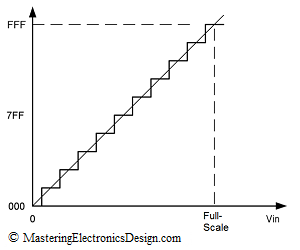
Figure 1
An ideal ADC transfer function is shown in Figure 1. This is a 12-bit ADC, but the steps are exaggerated for better viewing. There is no deviation from 1 LSB step, so the DNL is zero.
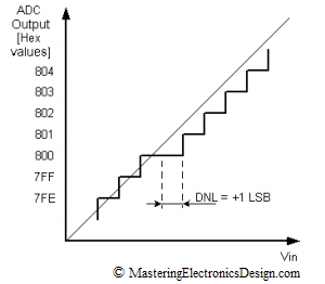
Figure 2
In Figure 2, the ADC holds the 0x800 hex output for two full steps. Since the deviation is towards the positive values on the X scale, and the ADC output holds the same value for an extra LSB, the Differential Non-Linearity is +1 LSB.
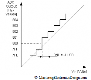
Figure 3
Figure 3 shows that the DNL migrated towards negative values for one LSB. Therefore, DNL in Figure 3 is -1 LSB. Since 0x800 is missing, there the ADC is categorized with missing codes. Such an ADC cannot be used for high precision applications.
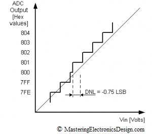
The DNL in Figure 4 is -0.75, because the 0x800 is still there, but for a shorter voltage range than one LSB. The code is still there, so the ADC can be used in precision applications.
Figure 4
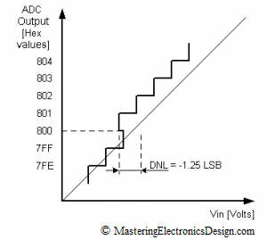
In Figure 5, the 0x800 step appears at lower voltage inputs than one LSB. The DNL is -1.25 LSB. It is clear that the ADC is highly non-linear. Moreover, it is categorized non-monotonic. High DNL values, positive or negative can increase the INL as well.
Figure 5
A non-monotonic DAC is highly undesirable, especially if the DAC is used in a closed loop application like servo or process controls. With a non-monotonic DAC the system may become unstable, or the control may suffer from jumpiness, jitteriness and overall difficult control handling.
The main rule for precision applications is to choose a component with a DNL less than one LSB. In this case, the ADC or DAC is assured monotonicity, no missing codes and a good linearity.




I really like your blog. I’ll be a frequent visitor.
Valuable thoughts and advices. I read your site with great interest.
thank u for this useful information
Doesn’t figure 1 contradict what’s on your topic about the LSB? I understand the graph has an offset of -1/2, but I think it should be FS instead of Vref in the x-axis. I mean, if you remove the offset, the last step will be on Vref and from what I understand, it shouldn’t.
Thoughts? (:
Good catch, Nobre. The last plateau should be labeled Full Scale, as shown in Fig. 2 of this article:
MasteringElectronicsDesign.com: An ADC and DAC Least Significant Bit (LSB)
Thanks. I corrected the figure.
Nice Article, good figures and examples.
Very Nice Article