This calculator determines the RMS value of a trapezoidal waveform. Figure 1 shows the waveform and its parameters. All you need to do is to input the time values t1, t2, t3, the signal period T and the signal amplitude Vp. Each time has to have the same units. If you set t1 in microseconds, as an example, all the other time values, t2, t3 and T have to have the same units, microseconds. Vp is a voltage level, in Volts, but the calculator can also be used for currents.
Analog Design
Why is the Op Amp Gain-Bandwidth Product Constant?
A recurring conversation I have usually starts with two questions: Why is the op amp gain-bandwidth product constant? And, how can we prove that?
The questions refer to the gain-bandwidth product behavior of an op amp after the cutoff frequency. As I showed in this article, MasteringElectronicsDesign.com: An Op Amp Gain Bandwidth Product, the gain bandwidth product describes the op amp gain dependency on frequency. The open loop graph is shown in Figure 1.
How to Calculate the RMS Value of an Arbitrary Waveform
Previous articles on MasteringElectronicsDesign.com talked about how to calculate the RMS of simple signals like a sine wave, trapezoidal and triangle signals, pulse and square signals. But, what about an arbitrary waveform? How do we calculate its RMS? Starting with the definition, as shown in previous articles, applying the integral, might not be an easy task. We need a different method. Enters the square root of the sum of squares.
The RMS value based on the square root of the sum of squares
If we have a few signals going through the same heating element, each signal heats the element independently of the other signals. This is valid, as long as the signals can be considered uncorrelated, that is, independent one of each other. The formula can be written as follows:
Design a Unipolar to Bipolar Converter the Easy Way with Microsoft Mathematics
Many analog circuits can be calculated with simple algebra. This may involve an equation or a system of equations, but the calculations are quite simple. Take the differential amplifier, as an example. In a previous article, MasteringElectronicsDesign: Design a Differential Amplifier the Easy Way with Mathcad, I showed how to design the differential amplifier by solving a system of two equations with two unknowns using Mathcad. Since then, readers asked me if there is any other substitute for Mathcad that they can use to solve the system of equations. And the answer is, yes, there is one.
Microsoft Mathematics is a free application which is loaded with features. Besides its graphing, math formulas and units converter, it has an equation solver that can easily handle systems of equations. By changing a few values and letting the application calculate the unknowns, a user can tweak his circuit to match the design requirements.
Tenma 72-7745 Multimeter Review
A few weeks ago I received a Tenma 72-7745 multimeter and I have been using it since. When I opened the box I liked it right away. Small and light, with plenty of functions, Tenma 72-7745 is a digital multimeter perfectly fit for anybody’s lab. It measures DC voltage, true RMS voltage, DC and AC current, resistance, capacitance, diodes, frequency, duty cycle and temperature. It has features like auto ranging, relative measurements and hold. The multimeter is part of a family, 72-7735, 72-7740 and 72-7745. It has a RS-232 interface, so that one can use a computer to log measurements. Here are a few tests and notes I made for this review.
Open-loop, Closed-loop and Feedback Questions and Answers
One of my readers posted the following questions in the comment section of MasteringElectronicsDesign.com: An Op Amp Gain Bandwidth Product.
I am doing a work on fully differential Negative feedback op-amp with capacitive divider configuration. I have some questions and confusions, can you please clarify?
What is the difference between closed loop gain and open loop gain, and are they dependent to each other?
How can we calculate the unity gain frequency if I have a 3-dB frequency of 100Hz and closed loop gain of 40dB?
Does the feedback factor (BETA) has importance with respect to any other parameters?
How will it help in finding the closed transfer function of the system assuming the op-amp as a single pole system?
The answers needed some space, more than the comment section could offer, so here is a post on the topics of op amp open-loop, closed-loop and feedback.
How to Derive the RMS Value of a Sine Wave with a DC Offset
I noticed a question posted on one of Yahoo’s Q&A sites, asking what is the RMS value of a sine wave with a DC offset. The chosen answer as being “the best” was actually wrong. The next comment, which was trying to correct “the best” answer, was wrong too. I am not going to post the Yahoo link here. What I can do, is to show how to derive the RMS value of such waveform.
Let’s derive first the RMS value of a sine wave with no DC offset
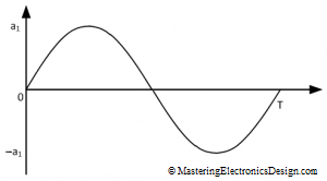
Let’s start with the RMS value of a sine wave, with no DC offset, which is shown in Figure 1. It is well known that the RMS value of a sine wave is 0.707 times the signal peak level, but how can you prove this?
As shown in this article, MasteringElectronicsDesign.com: How to Derive the RMS Value of a Trapezoidal Waveform, or other RMS articles in this website , let’s start with the RMS definition.


