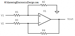
A differential amplifier frequent use is the amplification of the voltage difference between its inputs, while rejecting the common-mode level. However, the output common-mode level cannot be zero. The operational amplifier technological limitations, as well as the outside resistor tolerances let the common-mode voltage to make it to the amplifier output as an output error. As a consequence, the amplifier output voltage is the input signal difference times gain, plus the output common-mode voltage.
To reduce the output common-mode voltage one would have to match the resistors as much as possible, or at least their ratios: R2/R1 = R4/R3. One way to do this is to choose resistors with the lowest tolerance possible. Based on the resistor tolerances, this calculator will show the output common-mode voltage, Vocm, and the total voltage, Vout, at the differential amplifier output. Vocm will alter the ideal output voltage, which can be calculated when the resistors are perfectly matched. More about this subject can be found in these articles: The Differential Amplifier Common-Mode Error – Part 1 and Part 2. Also, in these articles there are the equations I used for this calculator.
Enter the resistors
| R1 = | kOhm | R2 = | kOhm |
| R3 = | kOhm | R4 = | kOhm |
Choose the resistors’ tolerance
| Tol = | % |
Choose V1 and V2
| V1 = | V | V2 = | V |
Calculate the output voltage, Vout, and the output common mode voltage, Vocm. This assumes a worst-case resistor mismatch due to tolerances.
| Vout = | V | Vocm = | V |
You can play with different values. If the tolerance is zero, Vocm is zero, and the differential amplifier output is the ideal output voltage, which is gain times the input difference. As you increase the tolerance, the output voltage is altered two fold: one, the gain is altered by the fact that R2/R1 is not exactly equal with R4/R3, and second, Vocm appears as an error in Vout. That is why, this calculator shows both values at the output, as a handy aid in design.
Some times we need a certain level for the output common-mode voltage. In this case the common-mode voltage is not an error, but a needed output voltage that helps us design a function. For example, the differential amplifier can be used to design a unipolar to bipolar converter. After you design this circuit, you can use this calculator to verify your design. More on this subject can be found in this article: Design a Unipolar to Bipolar Converter for a Unipolar Voltage Output DAC.


Hello
i really enjoyed this common mode voltage error calculator..
BUT maybe you should add that the Vocm can be positive or negative,
ciao
ian
Ahh and one more thing…
it appears that the common mode votlage error is NOT dependent on GAIN, but only resistor tolerance..
If this is the case than i guess we should have as mcuh gain as possible, which will reduce the effective output error due to the common mode votlage?
it obviously will affect the gain, but if offsets are more of a problem then higher gain seems to be the wya to go?
ciao
Hi Ian,
common mode voltage error IS dependent on gain, but indeed not proportionally to it. If you increase the gain by a factor 10, to common mode voltage error will increase much less than a factor 10.
So if you need a differential amplfier consisting of two gain stages, it is best to make as much gain as possible with the first amplifier to obtain a common mode voltage error on the output of the second stage that is as small as possible.
Ben.
Another great article. Thanks for the good work.
If you set R1 to 0 you get a NaN result, model has to be
changed to accommodate that.
Regards, Dana.
Nope, the model does not need to change. You get a NaN result because R1 appears at the denominator of the transfer function. What happens, physically, when you make R1 zero? R2 does not matter any more, and the output takes a value that corresponds to the current given by the difference between V1 and V2 divided by R3. So, there is a solution.
You get a NaN because the computer cannot divide by zero. It is the server response to a division by zero. If you want to find the solution, all you have to do is to make R1 very small, like 0.01 ohms. In that case the solution is Vout = 14.06V and Vocm = 12V (when the rest of the parameters are R3 = 1k, R2 = 20k, R4 = 20k, tolerance = 1%, V1 = 12.10V, V2 = 12V).
I am curious. Why would you make R1 zero in a differential amplifier and achieve such a high imbalance? Do you have a practical application?