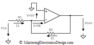
Figure 1
Widely used in Analog Design, the inverting amplifier in Figure 1 has a simple transfer function.
What is the proof of this function?
If we consider an ideal Op Amp, there is no current flow in the inverting input (see Figure 2). Therefore, I = 0 A and I2 and I1 are equal.
Moreover, being an ideal Op Amp, its gain is high, so the inverting input is at a virtual ground.
If you are not familiar with the concept of virtual ground, here is an explanation. Due to the high gain of the ideal Op Amp, on the order of 100,000 (or 100 dB), when the output is at a level of a few volts, the differential input can be around a few microvolts. Since the non-inverting input is connected to ground, with a potential of zero volts, the inverting input is very close to zero volts, hence the virtual ground. It is a ground, without the inverting input being galvanically connected to ground. That is why it is called “virtual”. For more, read this article MasteringElectronicsDesign: The Virtual Ground.
Using the previous equation, we can replace I1 and I2 as follows:
Rearranging this equation and considering V = 0V, the transfer function of the inverting amplifier is
Q. E. D.


Just a quick question, in this case, why can’t we do like voltage follower circuit, I mean, short R2 and remove R1.
Thanks,
yatin
You can do that, but then it is not an inverting amplifier anymore, it is a repeater. This article talks about the transfer function of the inverting amplifier.
I have a note about the voltage follower you describe here: Useful Operational Amplifier Formulas and Configurations.
That’s not a proof. You presume that both inputs are equal, but that’s a consequence of the proof, you can’t use that!
Well, I disagree. If you read this article again, you will notice that I used an ideal op amp. In an ideal op amp, the inverting input is at virtual ground. The virtual ground concept is well established in electronics design. The op amp inputs are considered equal in literature and everywhere else due to the op amp high gain and the feedback provided by R2. It is a physical consequence of feedback when the op amp output is not saturated. It is a shortcut used in finding the transfer function of circuits with op amps in DC domain. If you would start with finite gains for circuits with 3 or 4 op amps the equations would become cumbersome, so you have to use this shortcut.
To be clear, I included a link to my article The Virtual Ground, published some time ago, which shows, with equations, why the inverting pin is at a potential zero. In the same article I also show, how to derive the inverting amplifier transfer function when the operational amplifier gain is finite, and the result when the gain is large (click here). So, for a complete answer, read that article as well.
Explain more about the situation if it is not an ideal op amp and include resistor biasing.
Read this article, part two: MasteringElectronicsDesign: The Virtual Ground. As for resistor biasing, let me know which resistor you are talking about in reference to an op amp in an inverting configuration.
I’m a bit puzzled by the current :S
Should it be I2 = -I1 because they are flowing in opposite directions? Where does the minus suddenly come from?
Also since the op amp has high input impedance wouldn’t the current take the path of least resistance and bypass the thing by going through R2 to the output?
If I2 flows backwards and I1 forwards, summing at the node and none goes into the op amp, wouldn’t charge accumulate at the node too?
Thanks! 🙂
Correct. I2 = -I1. I will update the equation.
The currents are shown in opposite direction conventionally, each one leaving the source Vin and Vout. Of course, physically, they both flow in the same direction. I1 and I2 flow towards output, if Vin is positive, and flow towards input if Vin is negative. if you want, you can write I2 = I1 (and invert I1 in the figure) and then apply Kirchhoff equations: (Vout-V)/R2 = (V-Vin)/R1. The result is the same, Vout = -Vin * R2/R1.
You can also write I2 = -I1 as in the article. One can choose the current direction as he wants. In that case the equation becomes (Vout-V)/R2 = – (Vin-V)/R1. As you can see, the negative sign is now in front of the parenthesis.
is it not current flowing in = current flowing out? so I1 = I2 + 0
I answered this question in my post you reply to. It is just a convention. This is an inverting amplifier. If you show both currents in the same direction then you need to invert Vout.
What if I don’t have the resistor in one of the I1 or I2? For example, If I don’t have the resistor in I1, should I replace R1 in the equation with 0 or 1?
It depends on what “don’t have the resistor” means. If the resistor is missing, you replace it with a large value, say 100 Mohm. If the resistor is replaced by a simple wire, you replace it with a 0 ohm value. Keep in mind that a zero ohm value for R1 does not make sense for this circuit.