Design a Differential Amplifier Based on the Input and Output Voltage Level Requirements
The differential amplifier, also known as the difference amplifier, is a universal linear processing circuit in the analog domain. Why? Because you can achieve any linear transfer function with it. It can be reduced to a simple inverter, a voltage follower or a gain circuit. It can also be transformed in a summing amplifier.
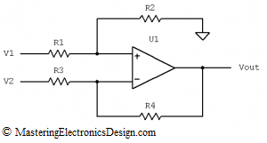
Figure 1
So, what is the common usage of the differential amplifier in Figure 1? When the resistor ratios are equal
the amplifier transfer function is
and the circuit amplifies the difference between the input signals.
However, there are times when the electronics designer is faced with the following design requirements: Given an input range of, say, -0.5V to 5.5V, the output has to swing between, say -1.25V and +2.365V. It is clear that this requires an amplifier with a certain gain and an offset different than zero. How can we design the differential amplifier to achieve such a function?
There are several methods to design this differential amplifier. In this article I will show how to design a differential amplifier using simple linear algebra.
In MasteringElectronicsDesign.com: Solving the Differential Amplifier – Part 2, I demonstrate that the same results can be accomplished with the coefficients identification method.
Still, no circuit analysis will be complete without the art of solving the circuit by inspecting it and finding the resistors one by one, based on the Operational Amplifier behavior and the laws of electricity. MasteringElectronicsDesign.com: Solving the Differential Amplifier – Part 3 shows this method in this series of how to design a differential amplifier articles.
A more general transfer function of this amplifier is given by the following expression.
You can find the proof of this function in this article, MasteringElectronicsDesign.com: The Differential Amplifier Transfer Function.
Let’s write down what we know.
If Vin1 = -0.5V, then Vout1 = -1.25V and
If Vin2 = 5.5V, then Vout2 = 2.365V,
where by Vin1 and Vin2 I noted the input range limits, and by Vout1 and Vout2 I noted the output range limits.
Let’s choose one of the input voltages of the differential amplifier in Figure 1 to be Vin, say V1. Practically, we will connect Vin to V1.
Because we have two instances that we know, Vin1 and Vin2 and the corresponding outputs, let’s rewrite the transfer function using these two instances.
This is a linear system of two equations with a lot of unknowns: R1, R2, R3, R4 and V2. Fortunately, in Electronics, we can make assumptions, based on real world realities.
From this system of equations, one can see that we don’t really need the resistor values, for now, but their ratios. The equations can be rewritten like this.
The number of unknowns is now down to three: R1/R2, R4/R3, and V2. Moreover, things get simpler if we note
So we have to solve for x and y in this system of equations:
After calculations, the result is
It is recommended to carry the dimensions in calculations, so that, if there are any errors, the dimensions will show that something happened during computations. For example, in the equation above, we know that y is dimensionless; therefore the result should be dimensionless. Indeed, 0.949V is a voltage, and since V2 is a voltage as well, y is dimensionless.
We can calculate y, if we choose V2 based on the supplies or reference voltages we have in the system. If, V2 = 2.5V, as an example, then R4/R3 = 0.38.
Knowing x and y, we can calculate R1/R2.
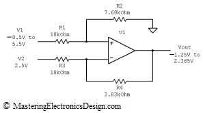
From now on, things are simple. Since we know the resistor ratios, choosing a resistor, say R3 = 10 kOhm, then R4 = 3.795 kOhm, or a standard value of 3.83 kOhm, with 1% tolerance. Also, choosing R1 = 10 kOhm, then R2 = 7.754 kOhm, or a standard value of 7.68 kOhm, with 1% tolerance.
The differential amplifier we just designed is shown in Figure 2.
Figure 2
>>> <<<


Today I searched for how to calculate the differential amplifier resistors. I read all 3 articles. You gave me 3 methods. Wow. More than I expected. Thank you for a great site.
I cannot agree more. Great job.
What is value Vcm when v1=5v and v2=5v