Why is the Op Amp Gain-Bandwidth Product Constant?

A recurring conversation I have usually starts with two questions: Why is the op amp gain-bandwidth product constant? And, how can we prove that?

The questions refer to the gain-bandwidth product behavior of an op amp after the cutoff frequency. As I showed in this article, MasteringElectronicsDesign.com: An Op Amp Gain Bandwidth Product, the gain bandwidth product describes the op amp gain dependency on frequency. The open loop graph is shown in Figure 1.

Read more

Design a Unipolar to Bipolar Converter the Easy Way with Microsoft Mathematics

Many analog circuits can be calculated with simple algebra. This may involve an equation or a system of equations, but the calculations are quite simple. Take the differential amplifier, as an example. In a previous article, MasteringElectronicsDesign: Design a Differential Amplifier the Easy Way with Mathcad, I showed how to design the differential amplifier by solving a system of two equations with two unknowns using Mathcad. Since then, readers asked me if there is any other substitute for Mathcad that they can use to solve the system of equations. And the answer is, yes, there is one.

Microsoft Mathematics is a free application which is loaded with features. Besides its graphing, math formulas and units converter, it has an equation solver that can easily handle systems of equations. By changing a few values and letting the application calculate the unknowns, a user can tweak his circuit to match the design requirements.

Read more

Measure a Bipolar Signal with an Arduino Board

Arduino is a popular family of open source microcontroller boards. Hobbyists, students and engineers all over the world use this platform to quickly design and prototype a microcontroller driven circuit. One of its interfaces with the analog world is the ADC. Since these boards are mostly designed around an ATMEL ATmega32 or ATmega168 microcontroller, the ADC has 8 inputs and 10-bit resolution, making it suitable for many applications.

From time to time I receive a message through my Contact page with the question, how to interface a sensor, or an outside circuit with the Arduino ADC? In most cases the answer is an interface between a bipolar circuit and the Arduino board. As the bipolar circuit output varies from some negative to a positive level, the Arduino ADC cannot measure this signal directly, because the ADC inputs can only be between 0V and the reference voltage.

In one of these messages a reader asked me how to build an interface between a board that has an output voltage of -2.5V to +2.5V and the Arduino ADC. He told me that the Arduino reference voltage is AVCC = 5V. He would like to measure the +/-2.5V signal with the Arduino board and direct the microcontroller to take some action based on the result.

Read more

Measure a Wheatstone Bridge Sensor Signal with an ADC

I received a message from one of my readers asking me to help with a Wheatstone bridge circuit. Since my response to him bounced back, and this being an interesting subject, I decided to write this article. Here is what he writes:

I found a circuit to condition the output of the Wheatstone bridge in the National ADC1205 datasheet, page 16. It uses an Op Amp configured as follows: V1 from the bridge thru 10K resistor to (–) input of Op Amp, 1.5Meg feedback resistor and Vout connects to the V- of the 5V ADC. V2 from the bridge connects directly to (+) input of the op amp and the V+ of the ADC.

The bridge V2-V1 is 0 mV to 30 mV. This is both at 5.000 V (0 mV) and V1 = 4.985 V, V2 = 5.015 V (30 mV). Please advise the equations to calculate how this works. Since the ADC is 5 V, I cannot see how the Vout can exceed that voltage. Is it true that Vout = 5.015 V when V1 = V2 = 5.015 V and ADC Out = 0 V?

The National ADC1205 is an obsolete component now, but the advice and application notes are still valid. We can use any ADC if we can correctly adjust Vref and the operating conditions. We can use an Arduino board as well, with its 10-bit ADC to achieve a complete system.

Read more

Build an Op Amp SPICE Model from Its Datasheet – Part 4

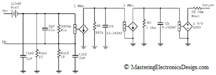
MasteringElectronicsDesign.com:Build an Op Amp SPICE Model from Its Datasheet – Part 1, Part 2, and Part 3 of this article show how to create a behavioral model of an operational amplifier based on the following parameters found in the datasheet: Input and output resistance, input capacitance, DC gain, offset voltage and gain bandwidth product. As an example I chose Analog Devices’ ADA4004 and built its behavioral model step by step. Figure 1 shows the model as we left off at the end of part 3.

ADA4004 macro model with two polesExpand this figure

Figure 1

Let’s continue building this model with some more parameters.

Read more

Build an Op Amp SPICE Model from Its Datasheet – Part 3

MasteringElectronicsDesign.com:Build an Op Amp SPICE Model from Its Datasheet – Part 1 and Part 2 show you how to build an Op Amp SPICE model based on the manufacturer’s datasheet. We talked about modeling the offset voltage, the input resistance and capacitance both common-mode and differential, the output resistance and the frequency domain behavior.

In Part 2, we left off at the open-loop bode plot. We saw that it resembles the datasheet. However, our op amp example, ADA4004 from Analog Devices, shows an extra pole after 1 MHz. Indeed, the phase starts dropping after 1 MHz and becomes 45 degrees at 17 MHz. Therefore, we need another pole in our model at 17 MHz.

Introducing the Second Pole

The pole can be introduced using the same technique we used in Part 2. We will use an RC Norton source. Since the DC open-loop gain is already set by the first pole, we only need to make sure that the choice of current and resistor does not affect the DC gain. This second pole influence has to be only at high frequencies. At low frequencies its gain should be 1, so that the overall open-loop gain remains 500000.

Read more

Build an Op Amp SPICE Model from Its Datasheet – Part 2

Part 1 of this article (http://MasteringElectronicsDesign.com/buildi-an-op-amp-spice-model-from-its-datasheet/) shows how to create a behavioral model of an operational amplifier based on the following parameters found in the datasheet: Input and output resistance, input capacitance, DC gain, and offset voltage. As an example I chose Analog Devices’ ADA4004. Let’s continue building this model to simulate the Gain Bandwidth Product.

Gain Bandwidth Product

The Gain Bandwidth Product, describes the op amp behavior with frequency. Op amps have a dominant pole, inserted by manufacturers on purpose, so that the op amp is stable at any gain down to zero dB. See this article for more details: MasteringElectronicsDesign.com:An Op Amp Gain Bandwidth Product. In that article I showed that ADA4004 has a cutoff frequency at 24 Hz. This frequency is not identified in the datasheet, but can be easily calculated from the open-loop minimum gain of 500000 and the gain bandwidth product of 12 MHz.

Starting with the cut-off frequency, the open loop gain versus frequency plot has a drop of 20dB for every decade of frequency. To simulate this we need to introduce this pole in our SPICE model. Question is, how?

Read more

Show Buttons
Hide Buttons
'