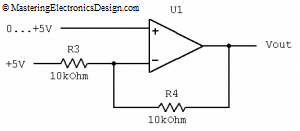
Unipolar to bipolar converters are useful when we have to have a unipolar component to do a certain job in a mixed signal design environment. For example, Digital to Analog Converters (DACs) may have the output voltage range 0 to 2.5 V, or 0 to 5 V, while the design asks for a range of –5 V to +5 V. To comply with this requirement, we have to design a unipolar to bipolar converter which will be inserted between the DAC output and the following bipolar stage. It looks like the circuit in Figure 1. How did I design it?
unipolar
Design a Bipolar to Unipolar Converter to Drive an ADC
Most Analog to Digital Converters have a unipolar input that can be a problem when designing bipolar circuits. Some common ADC input voltage ranges are 0 to 2.5 V, or 0 to 5 V. However, the analog circuit that drives the ADC can have voltage swings of, –1 V to +1 V, –2 V to +2 V , –5 V to +5 V, and so on. Bringing the ADC input below ground is a big No-No, because the current from input will flow through the chip substrate creating irreversible changes in the ADC and damage it. So, how do we connect a bipolar front end circuit with a unipolar ADC? Enters the bipolar to unipolar converter. Let’s design one.
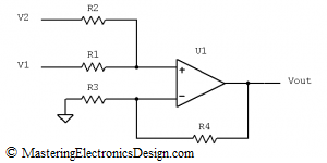
The converter can be designed with a summing amplifier, as in Figure 1. How do we calculate the resistors?
Figure 1


