The Common-Collector Amplifier Input and Output Resistance – The Proof

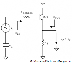
In this article I will show a method to deduce the input and output resistance of the common collector amplifier. The common-collector amplifier is a well known circuit (see Figure 1). It is mostly used as a buffer due to its high input resistance, small output resistance and unity gain. The equations derived in this article are symbolic, as is the derivation of any other formula in this website. Still, even if the resistances’ values are not numeric, the equations are intuitive enough to show the high input, low output resistance property of the amplifier.

common_collector_amplifier

Figure 1

Read more

Derive the Transfer Function of the Common Collector Amplifier with Thevenin’s Theorem

How to Apply Thevenin’s Theorem for Solving Circuits with Dependent Sources

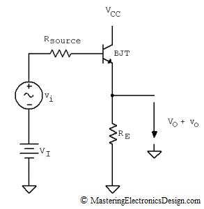
Besides its use to simplify and calculate currents in electrical circuits, Thevenin’s Theorem is also a great tool that we can use to derive transfer functions. This article will illustrate how to derive the small signal transfer function of the Common-Collector Amplifier with bipolar junction transistors (BJTs).

The circuit is shown in Figure 1. It is also called a repeater, so we expect that the calculated transfer function to be close to unity gain.

common_collector_amplifier1

Figure 1

Read more

Useful Operational Amplifier Formulas and Configurations

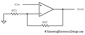
My friends advised me that it would be helpful to have on this site the most common operational amplifier configurations and transfer functions or formulas.  So, here they are.  This article is not just a simple collection of circuits and formulas.  It also has links to the transfer function proof for these circuits so I hope it will be very helpful.  Make sure you post a comment and let me know how I can improve this page.  This article will be updated, so do check it often.

Non-inverting Amplifier

non-inverting-amplifier-1

image0022

Note:  The proof of this transfer function can be found here:  How to Derive the Non-Inverting Amplifier Transfer Function.

Voltage Follower

voltage-follower-2

image0041

Note:  This configuration can be considered a subset of the Non-inverting Amplifier.  When Rf2 is zero and Rf1 is infinity, the Non-inverting Amplifier becomes a voltage follower.  When a resistor has an infinity value, in practice it means it is disconnected.

Read more

Show Buttons
Hide Buttons
'