The Non-Inverting Amplifier Output Resistance

It is customary to consider the output resistance of the non-inverting amplifier as being zero, but why is that? An Op Amp’s own output resistance is in the range of tens of ohms. Still, when we connect the Op Amp in a feedback configuration, the output resistance decreases dramatically. Why?

To answer these questions, let’s calculate the output resistance of the non-inverting amplifier.

It is widely accepted that the output resistance of a device can be calculated using a theoretical test voltage source connected at the device output. The input, or inputs, are connected to ground. Nevertheless, instead of using this method, let’s try a different one: The small signal variation method.

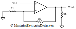
Figure 1 shows the non-inverting amplifier, which drives a load, RL. This circuit has an equivalent Thevenin source as in Figure 2.

non_inverting_amplifier

Figure 1

Read more

The Common-Collector Amplifier Input and Output Resistance – The Proof

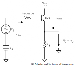
In this article I will show a method to deduce the input and output resistance of the common collector amplifier. The common-collector amplifier is a well known circuit (see Figure 1). It is mostly used as a buffer due to its high input resistance, small output resistance and unity gain. The equations derived in this article are symbolic, as is the derivation of any other formula in this website. Still, even if the resistances’ values are not numeric, the equations are intuitive enough to show the high input, low output resistance property of the amplifier.

common_collector_amplifier

Figure 1

Read more

Derive the Transfer Function of the Common Collector Amplifier with Thevenin’s Theorem

How to Apply Thevenin’s Theorem for Solving Circuits with Dependent Sources

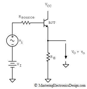
Besides its use to simplify and calculate currents in electrical circuits, Thevenin’s Theorem is also a great tool that we can use to derive transfer functions. This article will illustrate how to derive the small signal transfer function of the Common-Collector Amplifier with bipolar junction transistors (BJTs).

The circuit is shown in Figure 1. It is also called a repeater, so we expect that the calculated transfer function to be close to unity gain.

common_collector_amplifier1

Figure 1

Read more

Show Buttons
Hide Buttons
'