In allaboutcircuits.com forum an interesting circuit was posted. The question was, how to determine the transfer function, Vout/Vin?
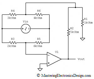
The circuit schematic was drawn as in Figure 1.
Figure 1
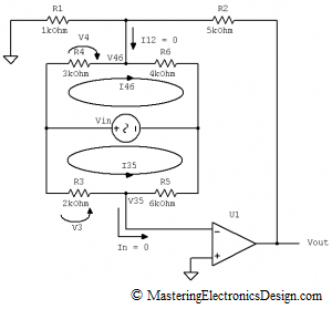
To make a point regarding its feedback and for clarity, I redrew it as in Figure 2.
Figure 2
Now, things started to make more sense. R1 and R2 are feedback resistors. Also, the bridge does not alter the feedback, because there is no current going through it from Vout to the bridge and to U1 input. Assuming that U1 is close to an ideal amplifier, its bias current in the inverting input is zero. Therefore, whatever current emerges from the R1 and R2 node, noted with I12, and goes to the bridge is zero. Also, the current that goes into the inverting input, In, has to be zero.
It becomes clear now that the circuit is very simple. The only currents that Vin generates are local currents, I46 and I35, through the bridge legs.
Let’s write the voltage difference V46-V35, which is the voltage that alters Vout. I will call it Vbridge.
This voltage alters Vout because it appears in the amplifier input. For that reason, Vout is given by the following equation:
| (1) |
The amplifier output adjusts Vout so that V35 = 0V. The inverting input is at a virtual ground, so we can write Vbridge as
| (2) |
If we find out V46 as a function of Vin, the circuit is solved. How do we calculate it?
By inspecting the bridge we can write V46 as follows:
| (3) |
The current through R3 and R5 is I35 and its value can be written as in the following equation.
With I35 known we can calculate V3.
Following the same train of thoughts, V4 is
By replacing V3 and V4 in (3), V46 in (2) and Vbridge in (1), the transfer function is
Q.E.D. (quod erat demonstrandum)
>>> <<<
This equation shows us that, if the bridge is balanced, when
the output voltage is zero. Hence, this circuit can be used for tuning, or for measurements, when one of the resistors in the bridge is a sensor. Due to the resistor ratios in the transfer function, the actual resistor value does not matter. What matters is the ratio of these resistors. As a consequence, the circuit is insensitive to temperature variations because, if all resistors are from the same technological process, the voltage at output does not change with temperature. If we choose a good operational amplifier, with a low temperature drift and low offset, this amplifier can be used in precision measurements.


nicely done, Adrian, good analysis.
I agree. I couldn’t find an explanation for this type of amplifier anywhere on the net. Thanks.
I followed this link from your post in the forum. I was curious to see how you found the formula you posted. It is rare to find such a well explained circuit. Thank you for your time.