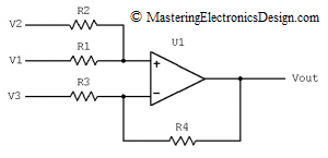
In a comment, one of my readers asked me what is the transfer function of the non-inverting summing amplifier in Figure 1, when R3 is connected to a reference voltage instead of ground. Well, this is a summing amplifier with a differential configuration.
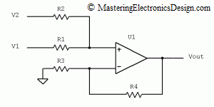
Figure 2 illustrates a non-inverting summing amplifier with the transfer function shown in equation (1). For a proof of this function read How to Derive the Summing Amplifier Transfer Function. In that article I showed a method to derive this function, by using the Superposition Theorem.
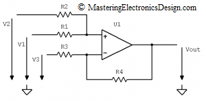
When R3 is connected to a potential other than zero, it is expected that the output will swing in the negative direction if the reference is positive. By how much? Well, let’s apply again the Superposition Theorem for the circuit in Figure 3 this time.
| (1) |
When R3 is connected to a potential other than zero, it is expected that the output will swing in the negative direction if the reference is positive. By how much? Well, let’s apply again the Superposition Theorem for the circuit in Figure 3 this time.
There are 3 voltage sources connected at the circuit inputs, V1, V2, and V3, all referenced to ground. The Superposition Theorem says that, the effect of all the sources in a circuit is equal with the sum of the effects of each source taken separately in the same circuit. This means that we have to calculate Vout1 when V2 and V3 are eliminated, Vout2 when V1 and V3 are eliminated, and Vout3 when V1 and V2 are eliminated. By elimination I mean replacing the source with a short-circuit (a wire). Then we have to add Vout1, Vout2, and Vout3 to find the transfer function.
I already calculated Vout1 and Vout2 in How to Derive the Summing Amplifier Transfer Function, when R3 was connected to ground. This means that we can use equation (1), as the sum Vout1 + Vout2. Let’s note this sum with Vout12, as in equation (2).
| (2) |
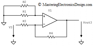
Next step is to connect R1 and R2 to ground. The new circuit will look like the one in Figure 4.
In this circuit Vout3 is the effect of V3 at the amplifier output, when V1 and V2 are zero. As a consequence, the circuit becomes an inverting amplifier with the transfer function shown in equation (3). When R1 and R2 are connected to ground they have no influence on the output other than, if the input bias currents are high, or when R1 in parallel with R2 do not mach R3 in parallel with R4, the output error could be elevated. One way to minimize the error is to choose an Op Amp with low input bias currents. This is a separate subject which will be discussed in a future article.
| (3) |
Read How to Derive the Inverting Amplifier Transfer Function for a proof of this function.
All that is left now is to add Vout12 and Vout3. Therefore, the transfer function of the circuit in Figure 2 is as follows:
| (4) |
This equation shows that the circuit in Figure 1 is a non-inverting summing amplifier and a differential amplifier. It performs the weighted sum of V1 and V2 and, at the same time, subtracts an amplified V3 from this sum.
For more on how to calculate the resistors read Solving the Summing Amplifier and Solving the Differential Amplifier – Part 1, Part 2, and Part 3. Also, the Summing Amplifier Calculator on this website gives you a faster way to solve such circuits.


My cousin recommended this blog and she was totally right keep up the fantastic work!
Thank you for this great site. It helped me a lot to understand op amps.
Thanks John. Glad you like it.
Spending some time to your weblog is extremely helpfull, Waiting your subsequent content.