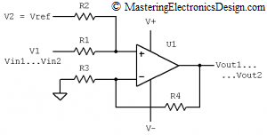
Several articles in this website describe the Summing Amplifier. In one of these articles, Solving the Summing Amplifier, I showed a numeric method to design a non-inverting summing amplifier based on its input and output voltage range requirements.
This article shows how to design a summing amplifier calculator and the mathematical relations it uses. You can find the calculator here:
JavaScript Summing Amplifier Calculator
Type the input voltage range, output range, a reference voltage and a choice of two resistors. The calculator gives you the answer for the remaining two resistors. The default values are for a bipolar to unipolar converter, which is explained in Design a Bipolar to Unipolar Converter to Drive an ADC.
What are the underlying equations?
When one needs to build a calculator, he/she has to solve the equations symbolically. As opposed to the numerical examples presented in Solving the Summing Amplifier and in Design a Bipolar to Unipolar Converter to Drive an ADC, we need to carry all the input variables through calculations when solving the system of equations.
The summing amplifier is shown in Figure 1. The design process starts with knowing the input voltage range and the output range. So, we know Vin1 and Vin2 at the amplifier V1 input, which are the input range limits. We also know Vout1 and Vout2. We need to choose a reference voltage, which will be connected at V2, usually from a clean voltage supply that we already have in the system.
Starting with the summing amplifier equation,
| (1) |
let’s write this equation for two instances, Vin1 and Vin2. For the proof of the transfer function read How to Derive the Summing Amplifier Transfer Function.
 |
(2) |
There are four resistors that need to be determined, but a closer look reveals that we only need to find the resistors’ ratio. If we note with k1 = R2/R1 and with k2 = R4/R3, the system of equations becomes:
 |
(3) |
This is a system of two equations with two unknowns, k1 and k2, which we can solve symbolically using linear algebra methods.
To do so, we first eliminate k2 by dividing the first equation by the second one. The resulting expression has one unknown, k1. After calculations, k1 results as
| (4) |
Replacing k1 in the first equation, we obtain one equation with one unknown, k2. The calculations are not difficult, since k2 + 1 is already isolated. So, k2’s expression is
| (5) |
We can clearly see that, dimension-wise, the relations are valid. Both k1 and k2 are resistor ratios. Each nominator and denominator has Volts dimensions, so the ratios are dimensionless, as expected. It is always a good idea to check the dimensions of each mathematical expression that you derive, especially if the calculations are symbolic. If the dimensions are right, the probability that the calculations are correct is quite high.
Knowing k1 and k2 we need to choose one pair of resistors to calculate the other pair. Let’s choose the ratios’ denominators, R1 and R3 and calculate R2 and R4. This is the reason why the calculator asks for a choice of resistors’ pair for solving the other pair. Taking into consideration k1 and k2 expressions, R2 and R4 result as
 |
(6) |
It is easy to see that, even if the system of equations has a solution (two equations with two unknowns always has a solution) not all the solutions are physically possible. R2 and R4 can result negative, or R2 can be undetermined (denominator zero). This is where the designer’s own reasoning comes to play. Beyond the mathematical solution, one has to think what needs to be done to have positive resistor values. The calculations presented in this article should help you.
For example, if Vout1 – Vout2 is smaller than Vin1 – Vin2, it means that the summing amplifier has to be an attenuator. Well, a non-inverting summing amplifier cannot be an attenuator. Due to k2 + 1, its gain is always higher than 1. Therefore, we need to attenuate the input signal with the R1 and R2 ratio. In this case R2/(R1+R2) attenuates the input signal, but we might need to make Vref smaller, due to the increase of R1/(R1+R2). The mathematical expression of R4 shows that, if we decrease Vref, the second fraction increases, so R4 might go onto the positive side.
If R2 is undetermined, it means that its expression denominator is zero. The calculator will show infinity, which means that R2 is disconnected. In the absence of R2, the circuit becomes a non-inverting amplifier.
I think this calculator will be a helpful tool for many electronics designers. Please let me know if you have any comments or suggestions for any upgrades.


What a great resource!