My friends advised me that it would be helpful to have on this site the most common operational amplifier configurations and transfer functions or formulas. So, here they are. This article is not just a simple collection of circuits and formulas. It also has links to the transfer function proof for these circuits so I hope it will be very helpful. Make sure you post a comment and let me know how I can improve this page. This article will be updated, so do check it often.
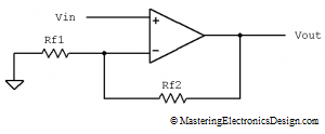
Non-inverting Amplifier
Note: The proof of this transfer function can be found here: How to Derive the Non-Inverting Amplifier Transfer Function.
Voltage Follower
Note: This configuration can be considered a subset of the Non-inverting Amplifier. When Rf2 is zero and Rf1 is infinity, the Non-inverting Amplifier becomes a voltage follower. When a resistor has an infinity value, in practice it means it is disconnected.
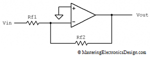
Inverting Amplifier
Note: The proof of this transfer function can be found here: How to Derive the Inverting Amplifier Transfer Function
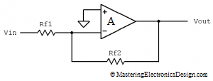
Inverting Amplifier with a Finite Op Amp Gain
where k = R2/R1
Note: The proof of this transfer function can be found here: MasteringElectronicsDesign.com:The Transfer Function of the Inverting Amplifier with a Finite Op Amp Gain
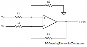
Differential Amplifier
Note: The proof of this transfer function can be found here: How to Derive the Differential Amplifier Transfer Function.
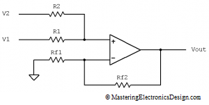
Non-inverting Summing amplifier
Note: The proof of this transfer function can be found here: How to Derive the Summing Amplifier Transfer Function.
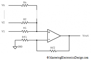
Non-inverting Summing Amplifier with N Inputs
where n is the number of inputs.
Note: The proof of this transfer function can be found here: The Transfer Function of the Summing Amplifier with N Input Signals.
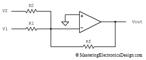
Inverting Summing Amplifier
Note: The proof of this transfer function can be found here: How to Derive the Transfer Function of the Inverting Summing Amplifier.
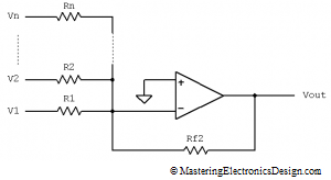
Inverting Summing Amplifier with N Inputs
where n is the number of inputs.
Note: The proof of this transfer function can be found here: How to Derive the Transfer Function of the Inverting Summing Amplifier.
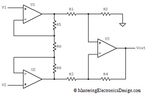
Instrumentation Amplifier
Note: The proof of this transfer function can be found here: How to Derive the Instrumentation Amplifier Transfer Function.
>>> <<<
Are there any other Op Amp configurations you would like to see listed here? Let me know.







cool blog
I bookmarked this link. Thank you for such a good job!
Nice work, my sincerest congratulations to Adrian! … Enhorabuena!
very nice work and very well appreciated for the effort
I was looking for a quick refresh and found this jewel.
Adrian, good job!
Thank you, Victor.
This document is a very useful one for every student……..
I would love to see an analysis of the Howland current source, especially the “improved” version with the small resistor separating the output of the op amp from the positive feedback resistor. Great resource!
That will take more than an answer here. I will put it in my schedule to write an article in the near future.
The cap multiplier and gyrator are interesting. great website.
I thought all the analog designers moved away.