Design a Unipolar to Bipolar Converter for a Unipolar Voltage Output DAC

Unipolar to bipolar converters are useful when we have to have a unipolar component to do a certain job in a mixed signal design environment.  For example, Digital to Analog Converters (DACs) may have the output voltage range 0 to 2.5 V, or 0 to 5 V, while the design asks for a range of –5 V to +5 V.  To comply with this requirement, we have to design a unipolar to bipolar converter which will be inserted between the DAC output and the following bipolar stage.  It looks like the circuit in Figure 1.  How did I design it?

unipolar_to_bipolar_converter_1Figure 1

Read more

Design a Bipolar to Unipolar Converter to Drive an ADC

Most Analog to Digital Converters have a unipolar input that can be a problem when designing bipolar circuits.  Some common ADC input voltage ranges are 0 to 2.5 V, or 0 to 5 V.  However, the analog circuit that drives the ADC can have voltage swings of, –1 V to +1 V, –2 V to +2 V , –5 V to +5 V, and so on.  Bringing the ADC input below ground is a big No-No, because the current from input will flow through the chip substrate creating irreversible changes in the ADC and damage it.  So, how do we connect a bipolar front end circuit with a unipolar ADC?  Enters the bipolar to unipolar converter.  Let’s design one.

The converter can be designed with a summing amplifier, as in Figure 1.  How do we calculate the resistors?

summing_amplifier1

Figure 1

Read more

The Common-Collector Amplifier Input and Output Resistance – The Proof

In this article I will show a method to deduce the input and output resistance of the common collector amplifier. The common-collector amplifier is a well known circuit (see Figure 1). It is mostly used as a buffer due to its high input resistance, small output resistance and unity gain. The equations derived in this article are symbolic, as is the derivation of any other formula in this website. Still, even if the resistances’ values are not numeric, the equations are intuitive enough to show the high input, low output resistance property of the amplifier.

common_collector_amplifier

Figure 1

Read more

Derive the Transfer Function of the Common Collector Amplifier with Thevenin’s Theorem

How to Apply Thevenin’s Theorem for Solving Circuits with Dependent Sources

Besides its use to simplify and calculate currents in electrical circuits, Thevenin’s Theorem is also a great tool that we can use to derive transfer functions. This article will illustrate how to derive the small signal transfer function of the Common-Collector Amplifier with bipolar junction transistors (BJTs).

The circuit is shown in Figure 1. It is also called a repeater, so we expect that the calculated transfer function to be close to unity gain.

common_collector_amplifier1

Figure 1

Read more

How to Apply Norton’s Theorem. Solving Circuits with Independent Sources

Norton’s Theorem is a powerful tool for solving electrical circuits.  Like Thevenin’s Theorem, it simplifies the circuit one needs to study and dramatically reduces potential calculation errors.

Norton’s Theorem states that networks with voltage and current sources, as well as resistors are electrically equivalent to one single current source and one single resistor in parallel with the source.  The theorem is valid for AC circuits, where instead of resistors there may be reactive components.  Since this theorem sounds very much like Thevenin’s Theorem, one can only imagine that Norton’s current source is equivalent with Thevenin’s voltage source.  Indeed, they are equivalent as we will see further.

To demonstrate how powerful this theorem is, let’s take the same circuit we studied in How to Apply Thevenin’s Theorem – Part 1.  This article describes how to apply Norton’s Theorem for a circuit with independent sources.  Circuits with dependent sources have to be treated differently by Norton’s Theorem.  We will see that in a future article.

independent_sources_13

Figure 1

Read more

How to Apply Thevenin’s Theorem – Part 2. Nested Thevenin Sources Method

What are Nested Thevenin Sources?  I came up with this name recently, while talking to an engineer about a design problem.  I just said it, and I liked it.  I then went and searched on Internet to see if anybody else used the term Nested Thevenin Sources before.  I did not find it so, here it is.  Let’s talk about it.

I borrowed the term from “nested loops” in the programming world.  The main idea is that you can use a method to accomplish a task inside another method of the same kind, hence the word nested.  As we saw in How to Apply Thevenin’s Theorem – Part 1, Thevenin’s Theorem is widely used to simplify the solving of a complex circuit.

With the Nested Thevenin Sources Method you first start to apply this theorem on a complex circuit.  The circuit is simplified, but it is still too complex to solve with loop and node equations.  Because of that, you apply the theorem again, and you simplify the circuit even more, and so on.  At some point, the circuit simplifies so much that, with just a glance, you can tell what is the Thevenin voltage and resistance.

After you find the most inner source Thevenin voltage and resistance, you make your way back and find the currents and voltages up to the highest Thevenin source in the rank.

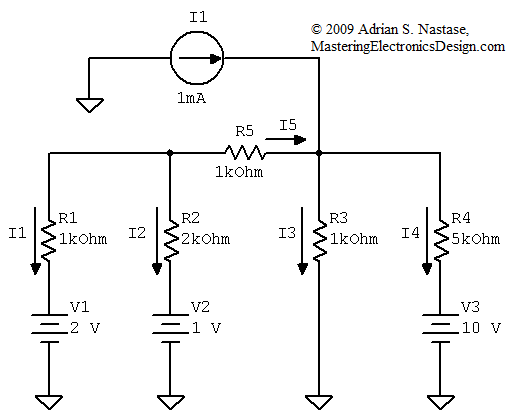
Let’s apply this method on the same circuit I used in Part 1 of this series.  The circuit is given in Figure 1.  The design asks to find all the currents in the circuit branches.  We will choose the same branch as in the previous article, R2 and V2.  Being a circuit with independent sources, we can choose any other branch.  For a circuit with dependent sources things are different, but we will talk about this in a future article.

independent_sources_11

Figure 1

Read more

How to Apply Thevenin’s Theorem – Part 1, Solving Circuits with Independent Sources

Thevenin’s Theorem makes it easy to study complex networks by simplifying the circuit to be studied.  It states that networks with voltage and current sources, as well as resistors are electrically equivalent to one single voltage source and one single resistor in series with the source.  The theorem is valid for AC circuits, where instead of resistors there may be reactive components.

Many people have problems applying this theorem.  In these series of articles I will demonstrate how simple this theorem is and how useful.

This article describes how to apply Thevenin’s Theorem for a circuit with independent sources.  An independent source is a source which does not depend on an external variable.  For example, the battery you buy from a store is an independent source.  It is build to source a certain voltage and will do that as long as it’s chemical process lasts.  Dependent sources are like those used to model transistors.  They are very useful to study the behavior of electronic circuits and components and have to be treated differently by Thevenin’s Theorem.  Read Derive the Transfer Function of the Common Collector Amplifier with Thevenin’s Theorem for a method for solving electrical circuits with dependent sources.

The circuit in Figure 1 has independent sources.  This circuit is composed of a mixture of sources, both voltage and current, to make it more challenging.  When solving this circuit, we need to use a method to find one, two or all currents flowing through the circuit branches.  A brute force approach is to write equations based on Kirchhoff’s circuit laws.  Doing so would require 5 equations, 3 loop equations and 2 node equations for 5 unknowns: I1, I2, I3, I4 and I5.

independent_sources_12

Figure 1

Here comes into play Thevenin’s Theorem.  Let’s choose one branch, say the current through R2.  For this, let’s redraw the schematic as in Figure 2.

Read more

Show Buttons
Hide Buttons
'