How to Derive the Instrumentation Amplifier Transfer Function

The Instrumentation Amplifier (IA) resembles the differential amplifier, with the main difference that the inputs are buffered by two Op Amps.  Besides that, it is designed for low DC offset, low offset drift with temperature, low input bias currents and high common-mode rejection ratio.  These qualities make the IA very useful in analog circuit design, in precision applications and in sensor signal processing.

instrumentation_amplifier_1

Figure 1

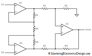
Figure 1 shows one of the most common configurations of the instrumentation amplifier.  Its clever design allows U1 and U2 operational amplifiers to share the current through the feedback resistors R5, R6 and RG.  Because of that, one single resistor change, RG, changes the instrumentation amplifier gain, as we will see further.  RG is called the “gain resistor”.  If the amplifier is integrated on a single monolithic chip, RG is usually left outside so that the user can change the gain as he wishes.  One example of such instrumentation amplifier is Texas Instruments’ INA128/INA129.

Read more

Differential Output Circuit

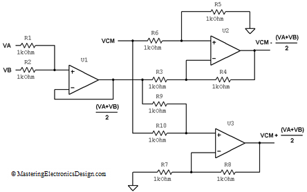
One of my readers asked me to explain how I designed a circuit I posted in a forum, as a solution to one of the member’s question.  The problem was about designing a circuit with 3 input signals, VA, VB and VCM.  The circuit had to output the sum and difference between VCM and the average of VA and VB as in the following expressions:

image0011 (1)

The solution I posted is the circuit in Figure 1.

differential_output_circuit

Figure 1

What is the easiest way to design this circuit?

Read more

Useful Operational Amplifier Formulas and Configurations

My friends advised me that it would be helpful to have on this site the most common operational amplifier configurations and transfer functions or formulas.  So, here they are.  This article is not just a simple collection of circuits and formulas.  It also has links to the transfer function proof for these circuits so I hope it will be very helpful.  Make sure you post a comment and let me know how I can improve this page.  This article will be updated, so do check it often.

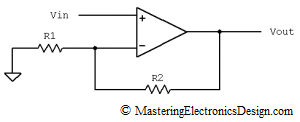
Non-inverting Amplifier

non-inverting-amplifier-1

image0022

Note:  The proof of this transfer function can be found here:  How to Derive the Non-Inverting Amplifier Transfer Function.

Voltage Follower

voltage-follower-2

image0041

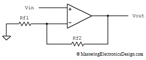
Note:  This configuration can be considered a subset of the Non-inverting Amplifier.  When Rf2 is zero and Rf1 is infinity, the Non-inverting Amplifier becomes a voltage follower.  When a resistor has an infinity value, in practice it means it is disconnected.

Read more

How to Derive the Transfer Function of the Inverting Summing Amplifier

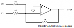
The inverting summing amplifier does exactly what its name says: adds the input signals and inverts the result.  This amplifier presents a major advantage versus the non-inverting summing amplifier.  The input signals are added with their own gain.  The disadvantage is the inversion of the sum, which might not be desirable in some cases.

inverting_summing_amplifier_1

Figure 1

Figure 1 shows the non-inverting summing amplifier with two inputs.  Its transfer function is shown in equation (1).

image0021 (1)

As you can see, this is a simple function. Each signal is added with its own gain created by the feedback resistor, Rf, and the corresponding resistor for that signal.  But, why is that?  Why is this transfer function a lot simpler than the non-inverting summing amplifier?  How can we derive this function?  What is the transfer function of the inverting summing amplifier with 3, 4, or n inputs?  This article answers all these questions.

Read more

The Transfer Function of the Non-Inverting Summing Amplifier with “N” Input Signals

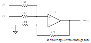
In a previous article, How to Derive the Summing Amplifier Transfer Function, I deduced the formula for the non-inverting summing amplifier with two signals in its input.  But what if we have 3, 4 or an n number of signals?  Can we add them all with one amplifier?

Theoretically, yes.  Practically, it is a different story.  There is a practical limit on how many signals can be summed up with one amplifier.  When the number of input signals grows, each signal component in the sum decreases in value. By the end of this article you will understand why.

summing_amplifier_1

Figure 1

We already saw that, for a summing amplifier with two input signals (Figure 1), the transfer function is

image002 (1)

If we need to add 3 signals, the circuit schematic looks like the one in Figure 2.  What is the transfer function of this summing amplifier with 3 inputs?

Read more

An ADC and DAC Differential Non-Linearity (DNL)

As in the case of INL, DNL is an important parameter of an ADC or DAC because it is a measure of their non-linearity.  DNL stands for Differential Non-Linearity and quantifies the ADC or DAC precision.

The term differential refers to the values an ADC takes between two consecutive levels.  When the input signal swings in any direction, the ADC samples the signal and its output is a stream of binary numbers.  An ideal ADC will step up or down one Least Significant Bit (LSB), without skipping any level and without holding the same decimal number past two or three LSBs. However, due to technological limitations, ADCs and even DACs are not ideal.  When that happens, the ADC’s linearity is severely impacted.  Therefore, DNL is defined as the maximum deviation from one LSB between two consecutive levels, over the entire transfer function.

In an electronic system, linearity is important.  When an ADC is non-linear, it brings imprecision in measurements.  If a DAC is non-linear, it restores a dynamic signal with high distortions.  Moreover, an accumulation of skipped levels, or high DNL, can increase the INL as well.

Figuring out the DNL value is quite simple. One has to measure the ADC response to a voltage value that would correspond to one LSB. For example, if we have a 12-bit ADC and the voltage reference is 2.5V, one LSB is given by the following equation.

image001

So, for each 0.6103 mV increase in the ADC input, the output hexadecimal value will increase with one.
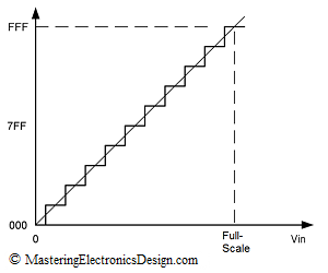
figure-1

Figure 1

An ideal ADC transfer function is shown in Figure 1.  This is a 12-bit ADC, but the steps are exaggerated for better viewing.  There is no deviation from 1 LSB step, so the DNL is zero.
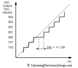
figure-2_2

Figure 2

In Figure 2, the ADC holds the 0x800 hex output for two full steps. Since the deviation is towards the positive values on the X scale, and the ADC output holds the same value for an extra LSB, the Differential Non-Linearity is +1 LSB.
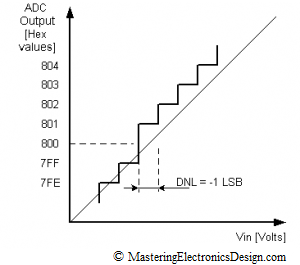
figure-2_3

Figure 3

Figure 3 shows that the DNL migrated towards negative values for one LSB. Therefore, DNL in Figure 3 is -1 LSB. Since 0x800 is missing, there the ADC is categorized with missing codes.  Such an ADC cannot be used for high precision applications.

The DNL in Figure 4 is -0.75, because the 0x800 is still there, but for a shorter voltage range than one LSB.  The code is still there, so the ADC can be used in precision applications.
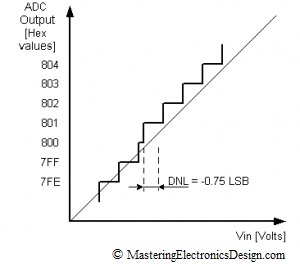
figure-3_2

Figure 4

In Figure 5, the 0x800 step appears at lower voltage inputs than one LSB.  The DNL is -1.25 LSB. It is clear that the ADC is highly non-linear.  Moreover, it is categorized non-monotonic.  High DNL values, positive or negative can increase the INL as well.
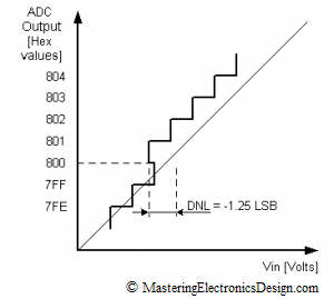
figure-2_4

Figure 5

A non-monotonic DAC is highly undesirable, especially if the DAC is used in a closed loop application like servo or process controls.  With a non-monotonic DAC the system may become unstable, or the control may suffer from jumpiness, jitteriness and overall difficult control handling.

The main rule for precision applications is to choose a component with a DNL less than one LSB. In this case, the ADC or DAC is assured monotonicity, no missing codes and a good linearity.

Show Buttons
Hide Buttons
'